Folding knife with locking mechanism

Inactive Publication Date: 2005-01-04
GERBER SAKAI
View PDF10 Cites 27 Cited by
  • Summary
  • Abstract
  • Description
  • Claims
  • Application Information

AI Technical Summary

Benefits of technology

It is an object of the present invention to provide a foldin

Problems solved by technology

However, only few locking mechanisms me

Method used


Image

  • Folding knife with locking mechanism
  • Folding knife with locking mechanism
  • Folding knife with locking mechanism

Examples


Embodiment Construction

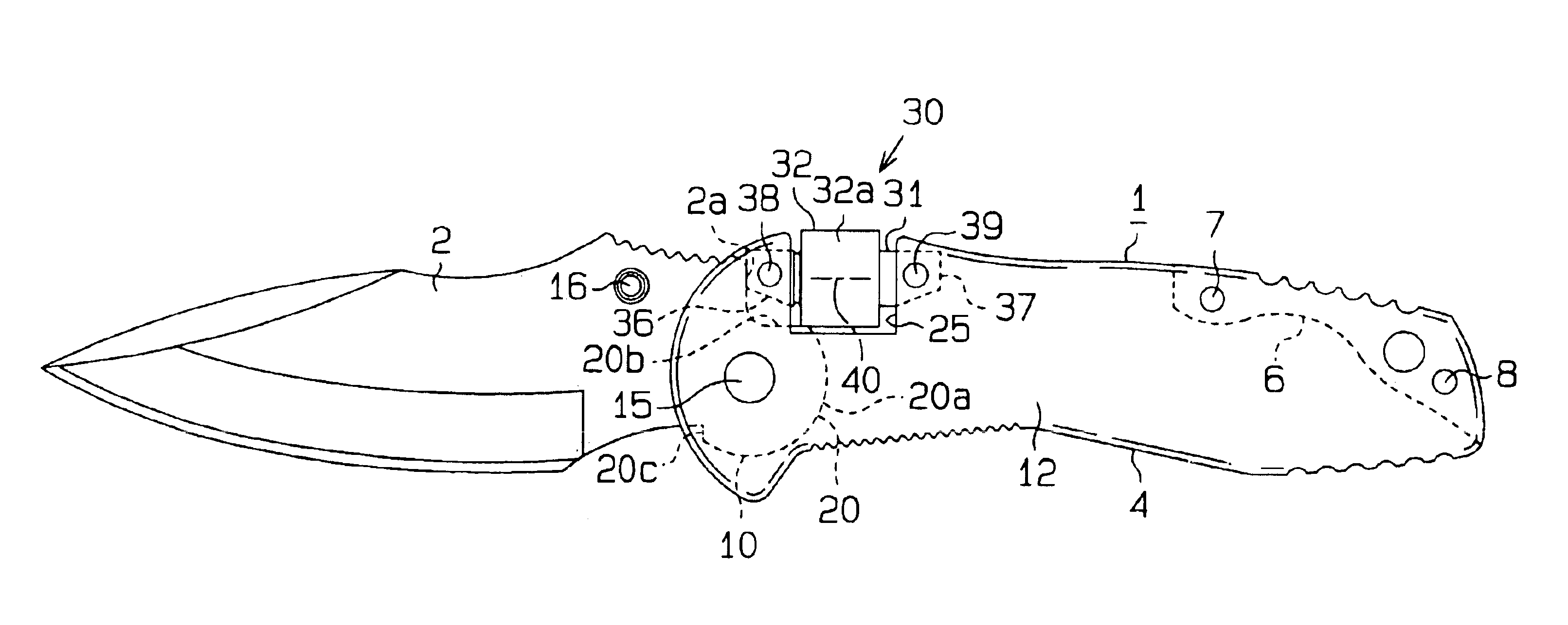
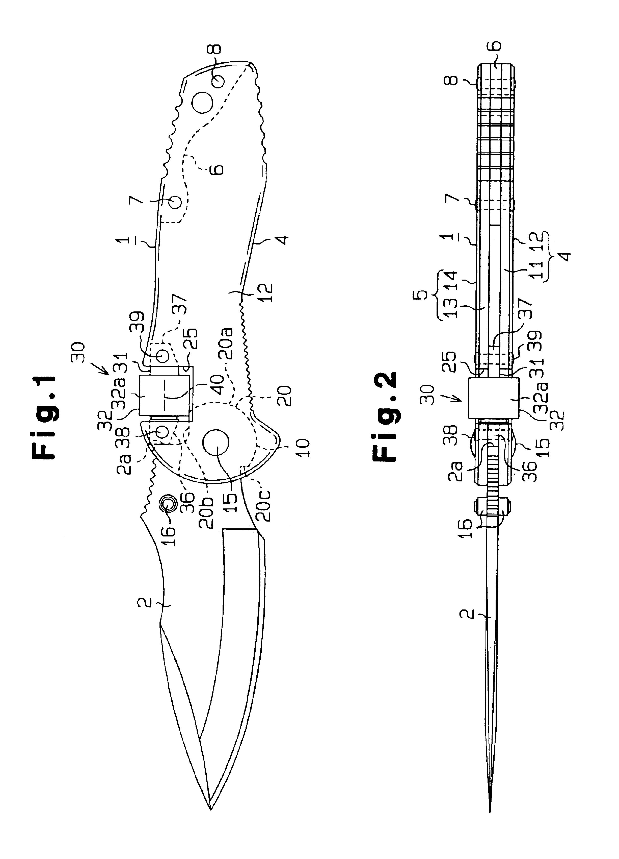
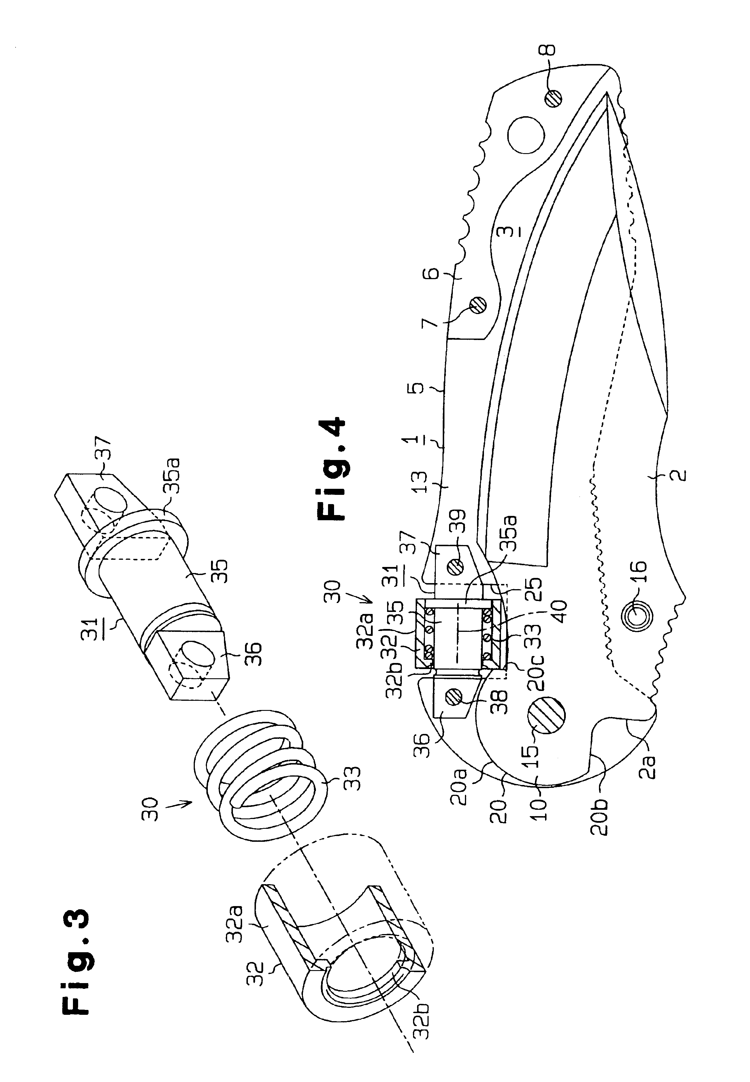
One embodiment of the present invention will now be described in accordance with FIGS. 1 to 7. As shown in FIG. 1, FIG. 2, and FIGS. 4 to 7, a folding knife includes a handle 1 and a blade 2, which is pivotally attached to the distal portion of the handle 1. The blade 2 is movable between a folded position (see FIG. 4), in which the blade is received within a receiving groove 3 of the handle 1, and an open position, (see FIG. 1 and FIG. 7) in which the blade extends out of the handle 1. The folded position corresponds to a non-use position of the blade 2 and the open position corresponds to a use position of the blade 2.

The handle 1 has first and second sidewalls 4 and 5; and a metal spacing plate 6 provided between the two sidewalls 4 and 5 in the vicinity of the basal portion of the handle 1. The two sidewalls 4 and 5 are joined together by first and second coupling pins 7 and 8 with the spacing plate 6 held in between the sidewalls 4 and 5. The first and second coupling pins 7 an...


PUM


Abstract

A folding knife includes a handle and a blade pivotally supported on the handle. A tang of the blade includes a cam surface. The cam surface has a substantially arcuate guiding portion and an engaging portion that extends continuously from one end of the guiding portion. A notch formed on an upper edge of the handle is provided with a lock mechanism. The lock mechanism includes a guide member, which is fixed to the handle in the notch, a hollow lock tube, which is supported on the guide member, and a coil spring, which is accommodated in the lock tube. The lock tube is movable along the longitudinal direction of the handle between a lock position for engaging the engaging portion and an unlock position separated from the engaging portion. When the blade is in the open position, the coil spring moves the lock tube toward the lock position. Thus, the blade is securely locked in the open position.

Description

BACKGROUND OF THE INVENTIONThe present invention relates to a folding knife equipped with a locking mechanism for locking the blade in an open position.An ordinary folding knife includes a handle and a blade pivotally supported at the distal end of the handle. A shaft, extending in a direction orthogonal to the blade, is attached to the distal end of the handle. A tang of the blade is pivotally supported by the shaft. The blade is movable between a folded position (non-use position), in which the blade is received within a receiving groove, and an open position (use position), in which the blade extends out of the handle.The above mentioned folding knife has a locking mechanism for locking the blade in the open position. Various mechanisms have been conventionally proposed and put to practical use as the locking mechanism. The locking mechanism must meet various requirements such as to be able to securely lock the blade, to be able to easily lock and unlock the blade, and to have a ...

Claims


Application Information

Patent Timeline
IPC IPC(8): B26B1/00B26B1/04
CPCB26B1/048
Inventor SAKAI, YOSHIRO
Owner GERBER SAKAI
Why Eureka
Try Eureka