Electronic level with audible and visual indicators

a technology of electronic level and visual indicator, which is applied in the direction of instruments, surveying and navigation, surveying instruments, etc., can solve the problems of lack of portability, difficulty in direct reading of level, and time-consuming use of traditional bubble level

Inactive Publication Date: 2005-01-04
DRAHOS LLOYD +1
View PDF23 Cites 55 Cited by
  • Summary
  • Abstract
  • Description
  • Claims
  • Application Information

AI Technical Summary

Benefits of technology

An electronic level with visual and audible indicators for measuring and indicating angular inclinations according to the present invention includes a frame having a generally rectangular configuration. The instrument includes a generally transparent disk mounted for rotation within the frame. The disk includes first and second sides, the disk being rotated by a weight attached thereto that is attracted to the Earth's surface by gravity. A plurality of opaque radial lines are imprinted upon the disk surface. A light-emitting source and a light sensor are mounted adjacent first and second sides of the disk, respectively, such that the disk is interposed therebetween. The light-emitting source directs light toward the light sensor along a path substantially perpendicular to the disk and the light sensor is capable of generating sensed signals responsive to the opaque lines. The particular sensed signals generated by the light sensor effectively identify the precise rotational position of the disk and thus the angular inclination of the instrument.

Problems solved by technology

However, a traditional bubble level can be extremely time-consuming and inconvenient to use.
The direct reading of the level is also difficult because it may be used in poorly lighted areas where the bubble cannot readily be seen.
Although assumably effective for their intended purposes, the existing devices suffer from disadvantages such as a lack of portability, relative crudeness in determining actual angular displacement, or a general fragility of construction which is unsuitable in the actual environment of the workplace.

Method used


Image

  • Electronic level with audible and visual indicators
  • Electronic level with audible and visual indicators
  • Electronic level with audible and visual indicators

Examples


Embodiment Construction

An electronic level with visual and audible indicators according the preferred embodiment of the present invention will now be described with reference to FIGS. 1 through 8c of the accompanying drawings.

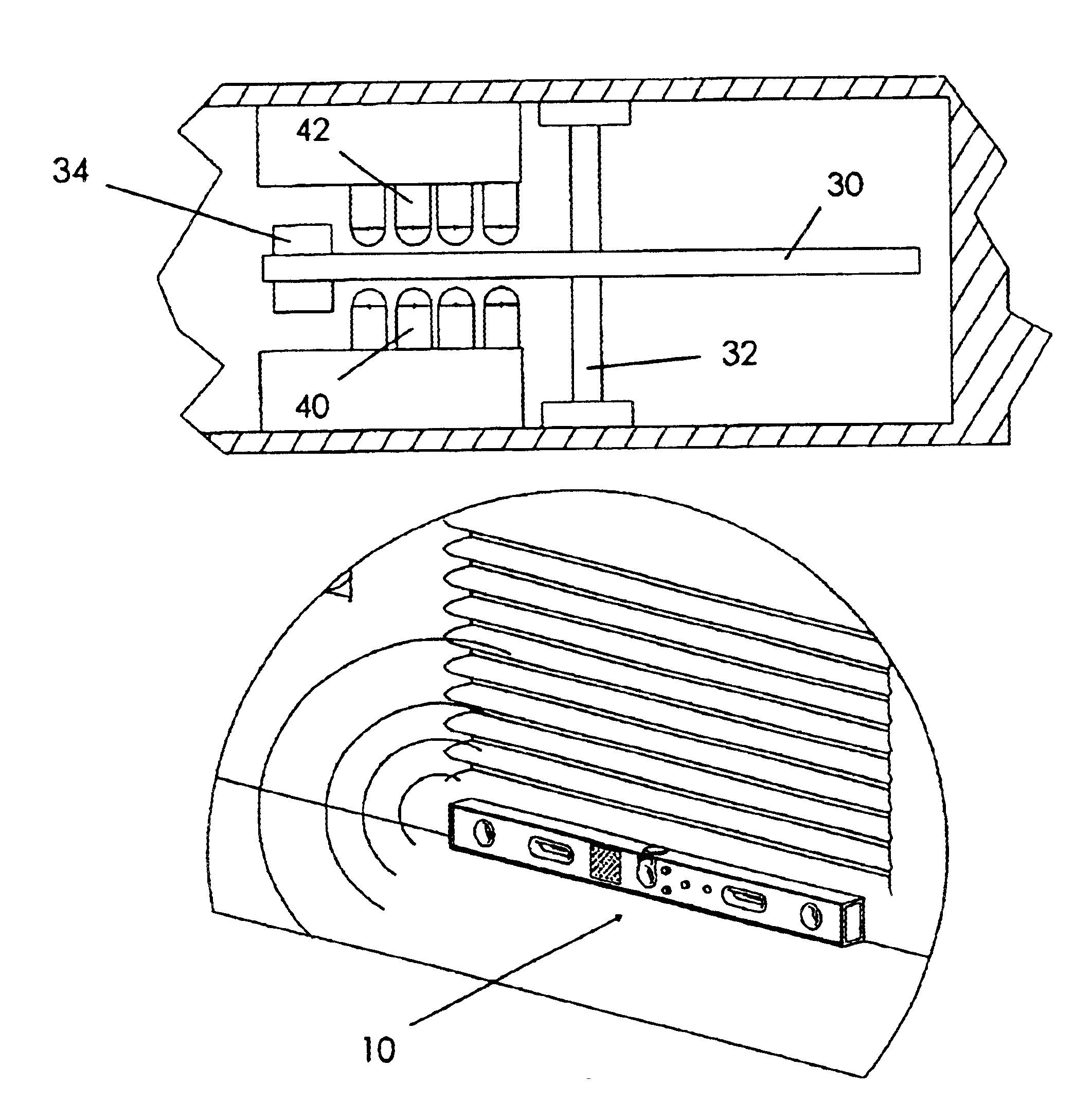
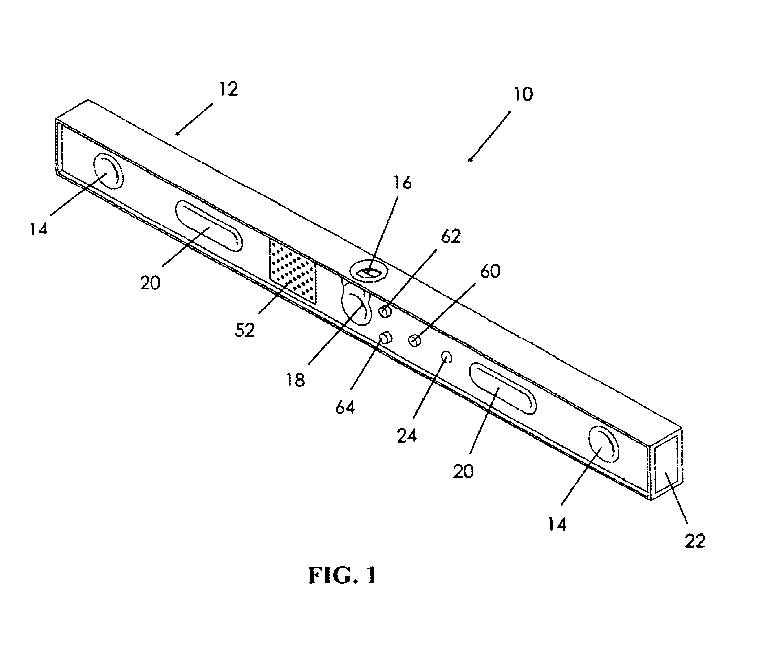
The electronic level 10 includes a rigid, substantially rectangular frame 12 constructed of rigid materials that resist deformity or bending. Preferably, the frame 12 is constructed of a metallic material although a wooden, plastic-graphite, poly-carbonate, or other plastic construction would also be suitable. The frame 12 includes a longitudinally elongate construction (FIG. 1). The preferred length from end to end is approximately four feet. The frame 12 defines an interior space for housing various sensing and indicating means as to be described below.

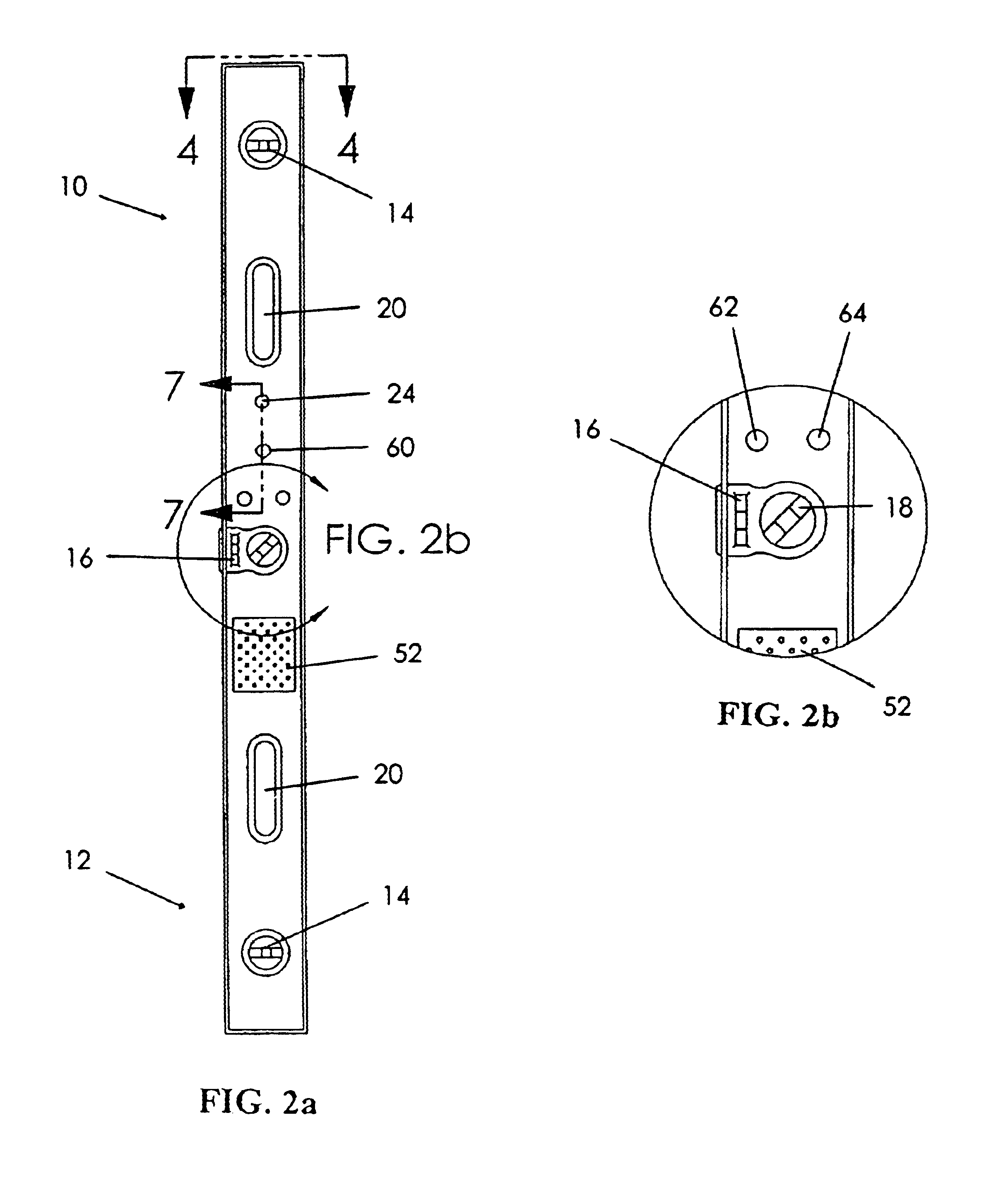
Multiple bubble vials are mounted to the frame 12 for visually indicating when the frame is in various angular alignments (FIGS. 1-2b). Each bubble vial 14 positioned adjacent a respective end of the frame 12 has a longitudinal axis ...


PUM


Abstract

An instrument for determining angular inclinations includes a rectangular frame having a generally transparent rotatable disk positioned therein. The disk includes a weight that is gravitationally attracted to the Earth's surface and circuitry for determining the disk's relative rotational position. A light source and sensor surround the disk and cooperate to determine the disk's angular position according to opaque lines imprinted on the disk's surface. The instrument includes a speech generator having a memory in which a plurality of audible messages corresponding to respective angular inclinations are stored. The instrument includes logic circuitry for determining an appropriate message to be generated according to the sensed position of the disk. This message is emitted through a speaker. The instrument further includes visual indicators relative to the angular inclination of the frame. Audible messages in multiple languages are stored in the speech generator memory and may be selectively accessed by a user.

Description

BACKGROUND OF THE INVENTIONThis invention relates generally to angular measurement devices and, more particularly, to an electronic slope indicating instrument which provides both visual and audible indications of angular measurement.Bubble levels have traditionally been used to indicate alignment with a horizontal or vertical axis. Such a level typically includes one or more bubble vials in which the position of a gas bubble relative to a pair of transverse lines indicates a respective alignment. However, a traditional bubble level can be extremely time-consuming and inconvenient to use. Often the workpiece whose angular alignment is in question must be adjusted at some distance from the point of measurement, requiring the worker to travel repeatedly from the point of adjustment to the place where the level is located. The direct reading of the level is also difficult because it may be used in poorly lighted areas where the bubble cannot readily be seen.Various types of electronic ...

Claims


Application Information

Patent Timeline
Patent Type & Authority Patents(United States)
IPC IPC(8): G01C9/00G01C9/06G01C9/12
CPCG01C9/06G01C9/12G01C2009/066
Inventor DRAHOS, LLOYDDRAHOS, LISA
Owner DRAHOS LLOYD
Why Eureka
Try Eureka