Baler with resilient-wheeled platen

Inactive Publication Date: 2005-01-04
SIMPSON EDWIN K
View PDF12 Cites 6 Cited by
  • Summary
  • Abstract
  • Description
  • Claims
  • Application Information

AI Technical Summary

Benefits of technology

The present invention overcomes the deficiencies of the prior art by providing a compactor/baler with a platen on wheels that support some of the weight of the platen to reduce sliding frictional forces. In this manner, the compactor/baler uses more of the available power in the compacting process, with less power wasted by friction.

Problems solved by technology

The wheels support a substantial portion of the weight of the platen to mitigate sliding friction, but the sliding surface s

Method used


Image

  • Baler with resilient-wheeled platen
  • Baler with resilient-wheeled platen
  • Baler with resilient-wheeled platen

Examples


Embodiment Construction

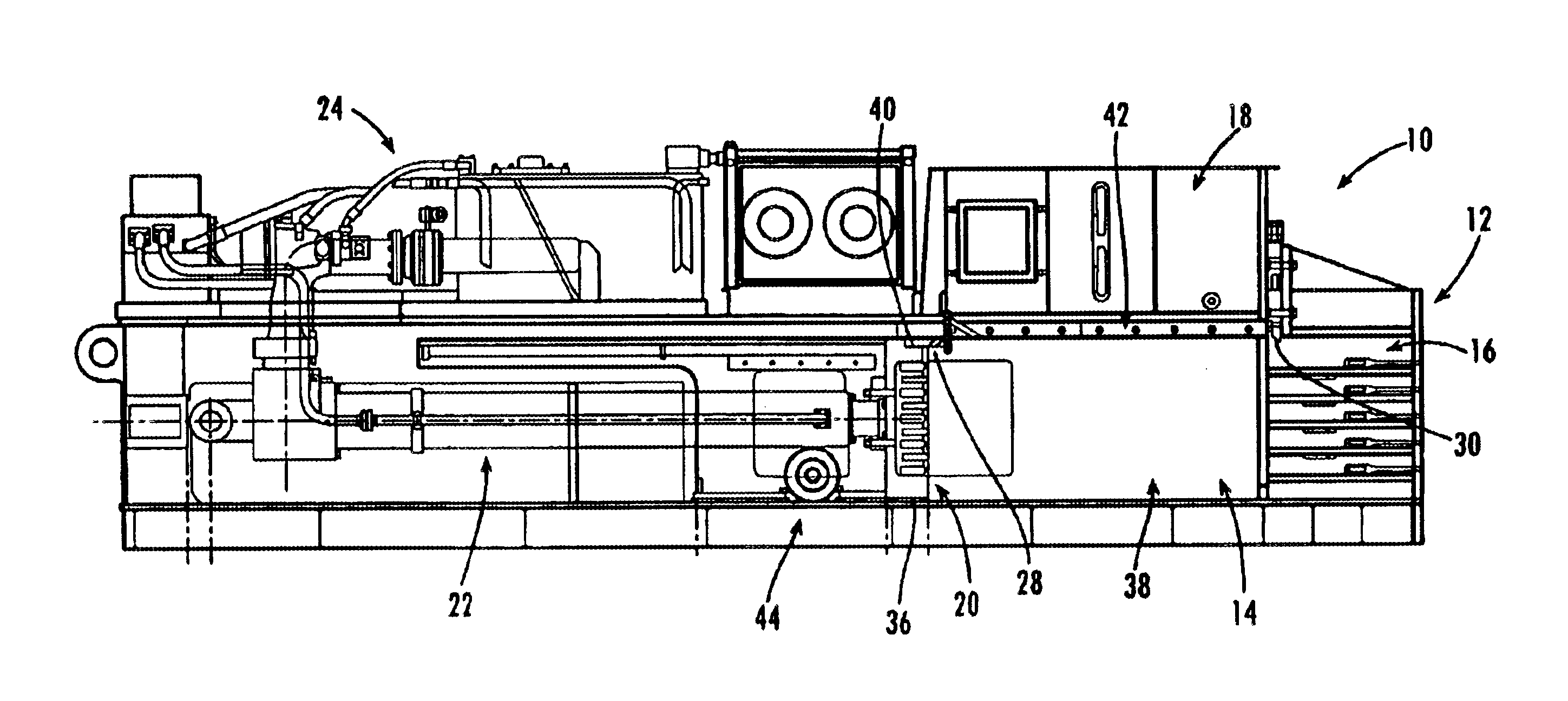
The present invention provides for compacting waste materials into bundles that can be baled and efficiently hauled away and disposed of. For example, the present invention can be used by facilities such as recyclers, printers, distribution centers, and grocery stores for processing waste materials such as paper, cardboard, municipal solid waste, and / or other refuse. Of course, the invention can be used by other facilities or persons for compacting other types of materials, with or without the baling process.

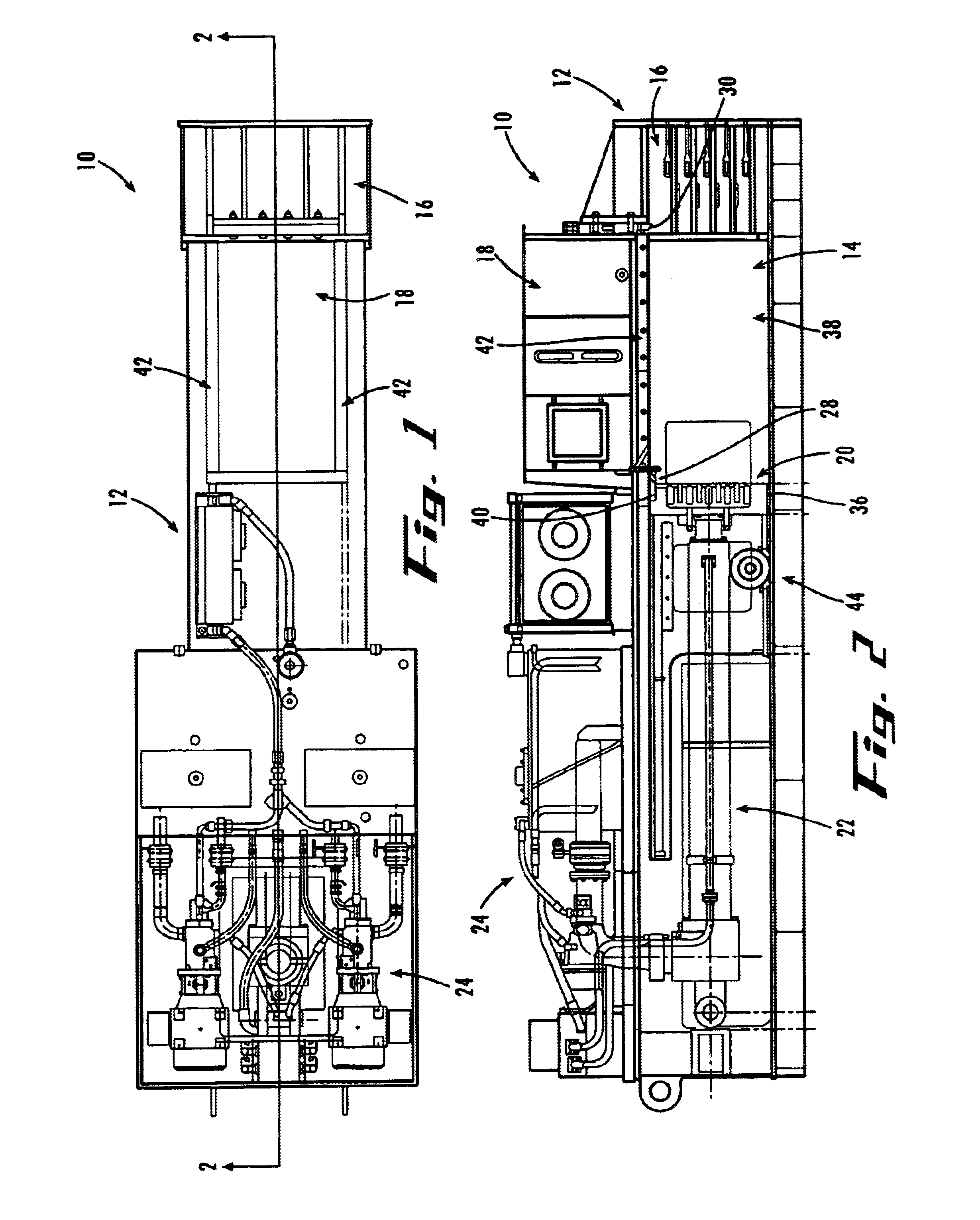
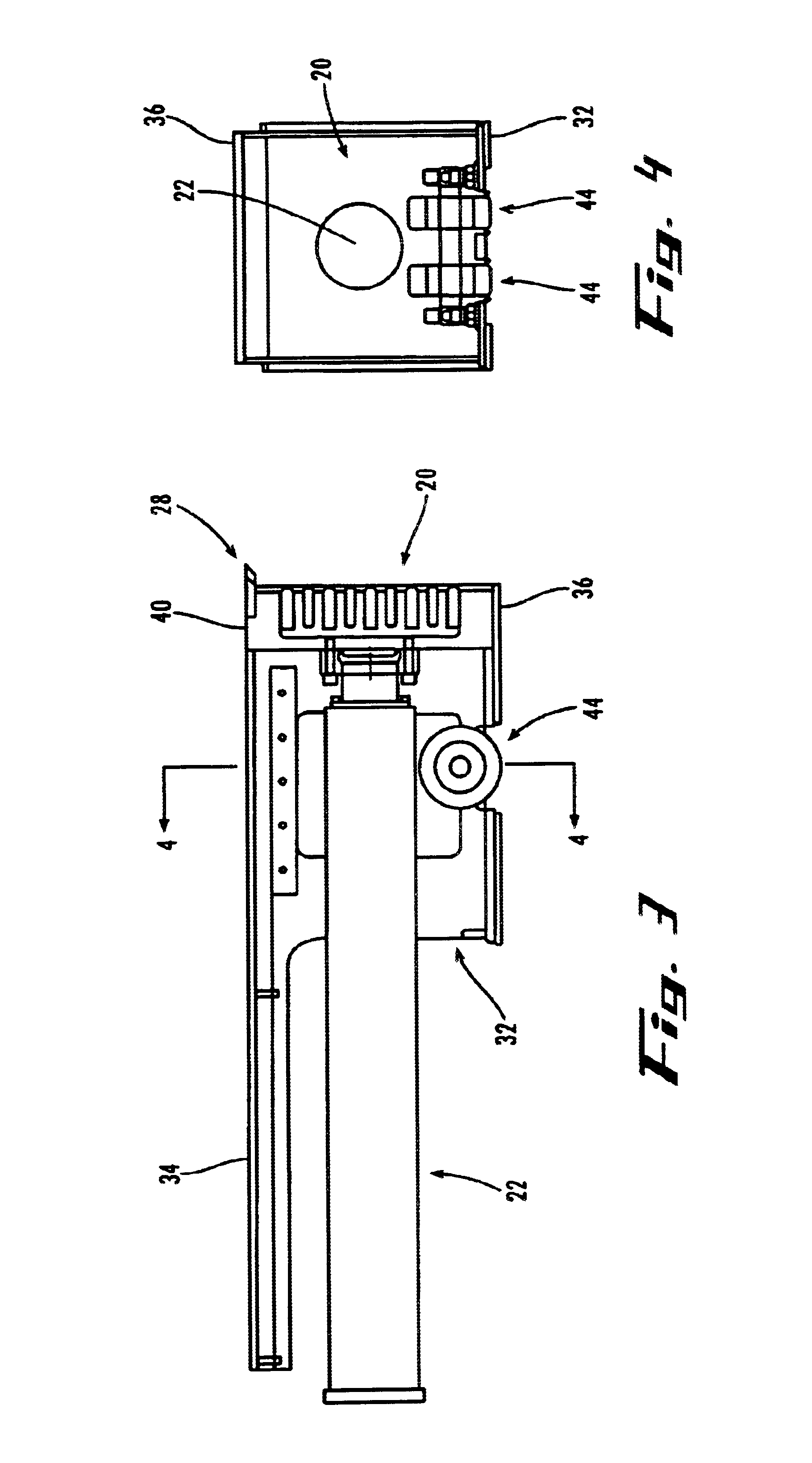
Referring now to the drawing figures, wherein like reference numerals represent like parts throughout the several views, FIGS. 1 and 2 show an exemplary embodiment of the present invention, referred to generally as a compacting machine 10. The machine 10 has a machine frame 12 with a charging chamber 14, a compression chamber 16, a hopper 18, a baling section (not shown), a platen 20. Also, the machine 10 has an actuator 22 for moving the platen, and a control system 24 for oper...


PUM


Abstract

A frame (12) with a charging chamber (14) for receiving a load of waste material, a platen (20) that moves in the charging chamber to compact the material load, and one or more wheels (44) rotatably coupled to the platen. The charging chamber (14) has a floor (34), the platen (20) has a bottom (32) that slidably contacts the floor and supports enough of the weight of the platen on the floor that none or little of the material can pass under the platen, and the wheels (44) support a substantial portion of the weight of the platen on the floor to mitigate sliding friction. The wheels (44) are made of a resilient material and deform from an unloaded state to a loaded state when supporting the substantial portion of the weight of the platen (20).

Description

TECHNICAL FIELDThe present invention relates generally to waste reduction equipment and, more particularly, to a machine for compacting and baling waste such as paper by horizontally moving a platen on resilient wheels.BACKGROUND OF THE INVENTIONFacilities such as recyclers, printers, distribution centers, and grocery stores handle large amounts of waste materials such as paper, cardboard, municipal solid waste (typical office and / or household trash), and other refuse. These and other facilities often use baler machines for compacting and baling the waste materials into bundles that can be efficiently hauled away and disposed of.Conventional balers include a compacting chamber and a ram-operated platen that moves horizontally to downwardly shear and compact the material in the chamber. In one known type of baler, the platen slides along the bottom of the chamber. This design provides a close fit between the platen and the chamber walls so that debris does not get under the moving pl...

Claims


Application Information

Patent Timeline
IPC IPC(8): B30B9/00B30B9/30B30B15/04
CPCB30B9/3021B30B15/08B30B15/041
Inventor SIMPSON, EDWIN K.
Owner SIMPSON EDWIN K
Why Eureka
Try Eureka