Apparatus and method for gravel packing

Inactive Publication Date: 2005-01-04
SUPERIOR ENERGY SERVICES LLC
View PDF30 Cites 13 Cited by
  • Summary
  • Abstract
  • Description
  • Claims
  • Application Information

AI Technical Summary

Benefits of technology

This apparatus and method has the advantage of not only reducing the incidence of sand bridge formation and packing gravel around any sand bridges that may be formed, but also has the advantage o

Problems solved by technology

Many prior art gravel packing methods and devices are incapable of completely packing a well penetrating an unconsolidated or poorly consolidated subterranean oil and gas reservoir.
The problem of incomplete packing often occurs as a result of the formation of sand “bridges” in the interval to be packed, which prevents the placement of sufficient sand below the bridge, in the case of top down gravel packing, or above the bridge in the case of bottom up gravel packing.
While the method and apparatus disclosed in this prior art reference may help to divert the sand and fluid slurry mixture around any sand bridges, which may be formed, it does not reduce the incidence of sand bridge formation.
Furthermore, the apparatus employed in this technique requires the use of additional shunt tubes secured to the outside of the sand screen, which block a portion of the sand screen.
This has the disadvantage of blocking a portion of the passageway through

Method used


Image

  • Apparatus and method for gravel packing
  • Apparatus and method for gravel packing
  • Apparatus and method for gravel packing

Examples


Embodiment Construction

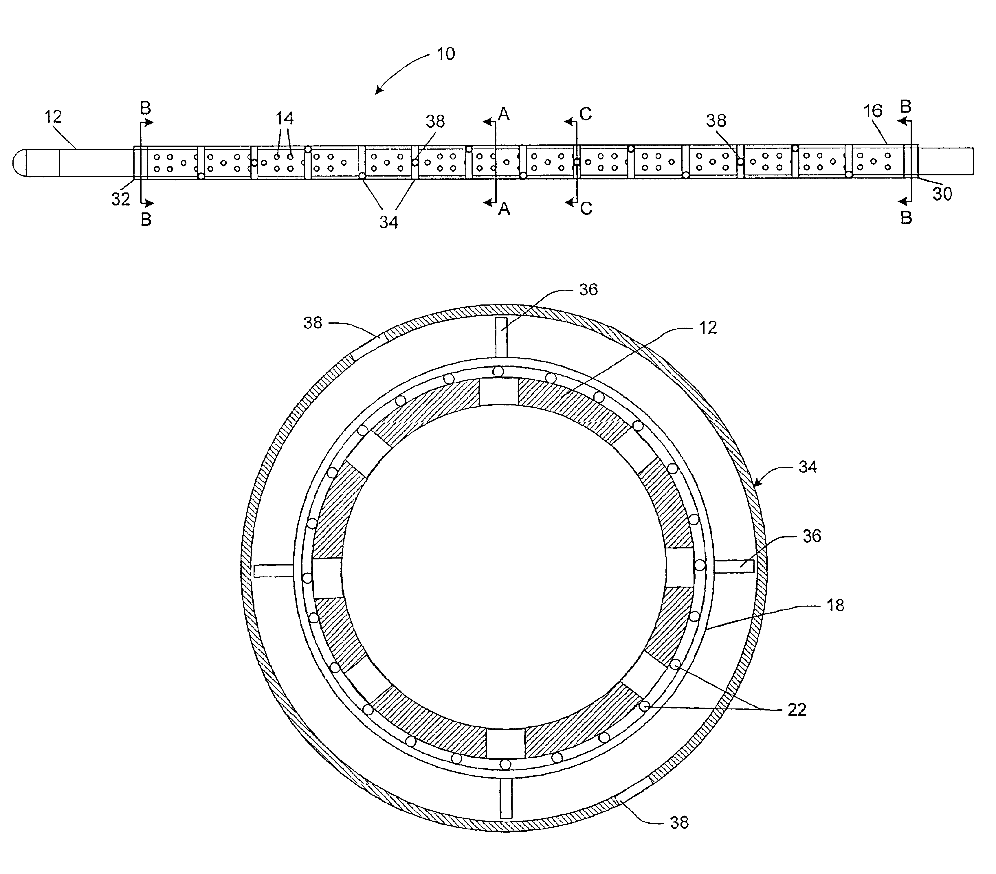
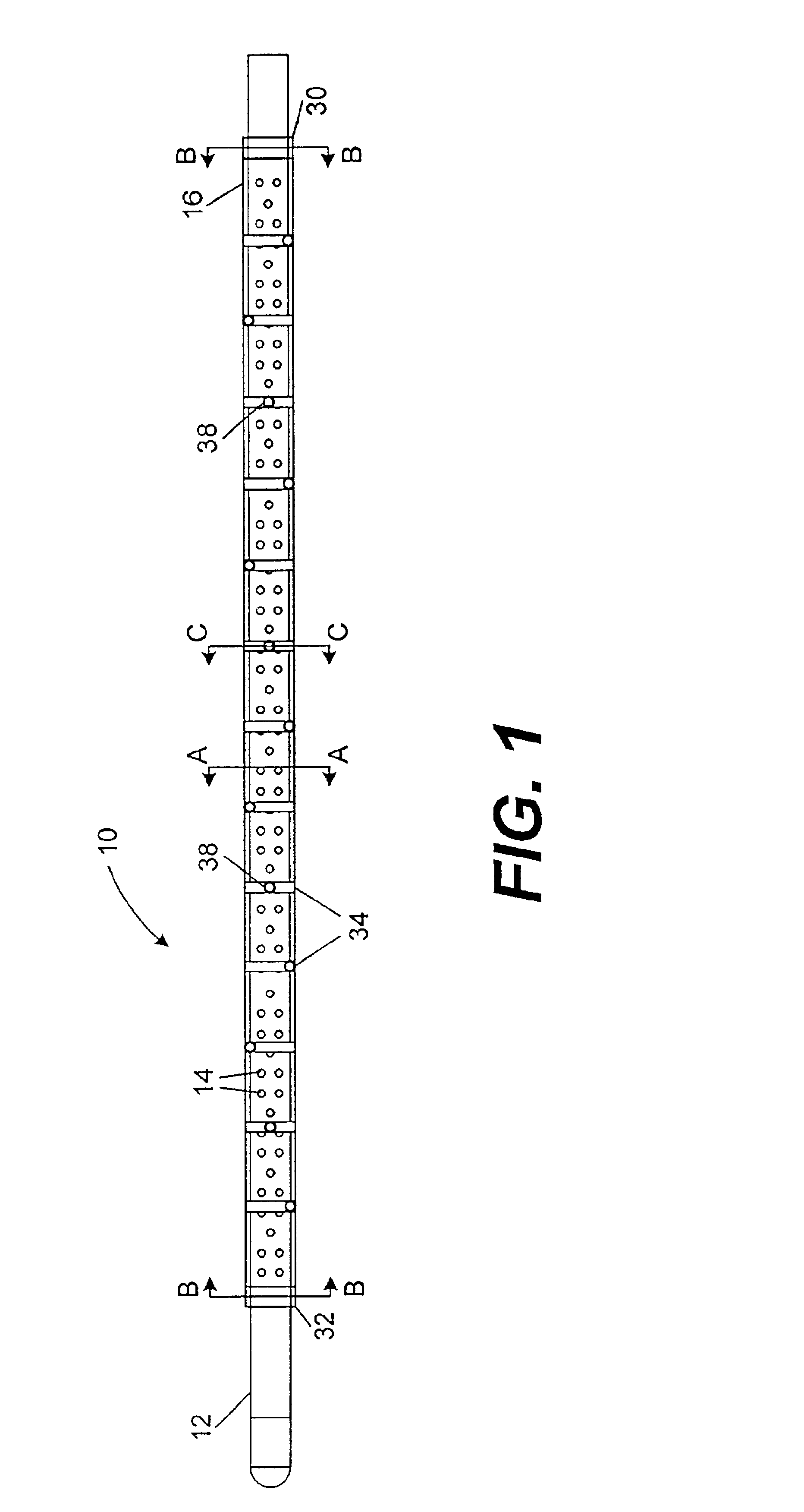
Referring now to the drawings, the details of preferred embodiments of the invention are schematically illustrated. FIG. 1 illustrates the apparatus for gravel packing in accordance with the present invention. The apparatus is shown generally by reference numeral 10.

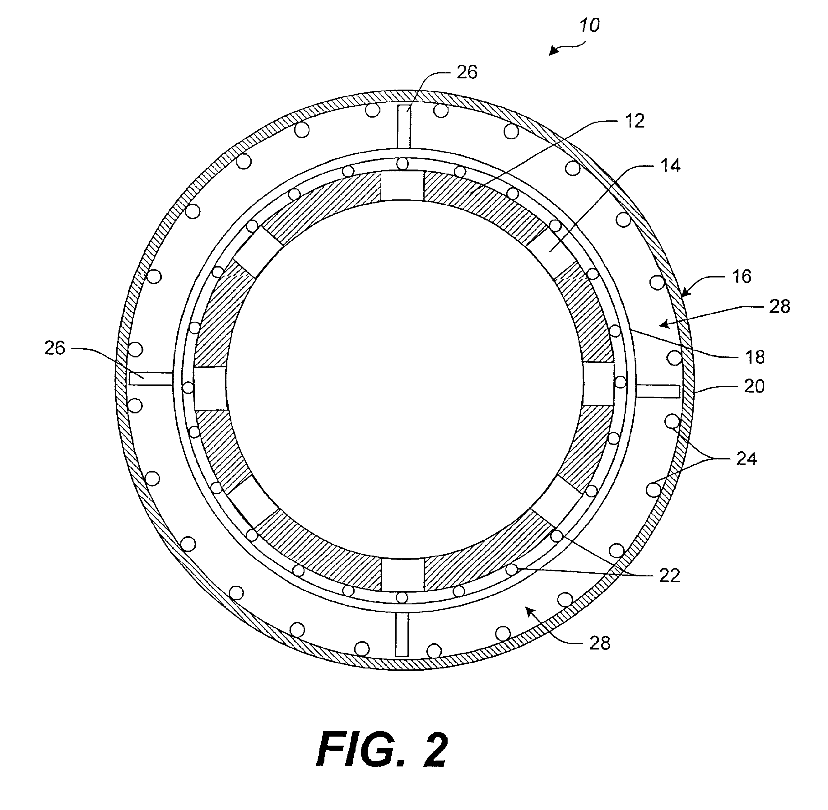
The apparatus 10 includes a base pipe 12, which is also known as a production pipe. The base pipe 12 is preferably formed of a steel alloy. The base pipe 12 has a plurality of apertures 14, which are preferably approximately 0.25-0.50 inches in diameter. The apertures 14 provide a passageway for hydrocarbons to enter into the production pipe 12. The apparatus 10 also includes a dual-wall screen 16, which is provided for blocking gravel and other matter from entering into the production pipe 12.

The dual-wall screen 16 includes an inner screen jacket 18 and an outer screen jacket 20, as shown in FIG. 2. The inner screen jacket 18 and the outer screen jacket 20 are substantially permeable to fluids and impermeable to sand. ...


PUM


Abstract

An improved apparatus and method for gravel packing is provided. The apparatus includes a substantially tubular-shaped base pipe having a plurality of apertures disposed along part of its length and a dual-wall sand screen coaxially secured to the base pipe. The dual-wall screen is substantially permeable to fluids and impermeable to sand. The apparatus provides a plurality of fluid permeable channels formed within the sand screen, which are disposed along the entire length of the screen. Each channel has an associated plurality of ports spaced along discrete intervals of the screen, which communicate with an annulus formed between the apparatus and the wellbore. The method provides for injecting a sand and fluid slurry mixture through the screen and out of the ports. This design reduces the incidence of sand bridge formation, and packs gravel around any sand bridges, which may be formed.

Description

FIELD OF THE INVENTIONThe present invention relates generally to an apparatus and method for gravel packing, and more particularly to an improved apparatus and method, which reduces the incidence of sand bridge formation, which occur prior to the completion of successful gravel packs, and provides successful prepacking between screens while the apparatus is in the well.BACKGROUND OF THE INVENTION TECHNOLOGYMany prior art gravel packing methods and devices are incapable of completely packing a well penetrating an unconsolidated or poorly consolidated subterranean oil and gas reservoir. With such methods and devices, the annulus between the sand screen and the casing for in-casing gravel packs or between the screen and the side of the hole for open hole or under-reamed gravel packs are not completely packed. The problem of incomplete packing often occurs as a result of the formation of sand “bridges” in the interval to be packed, which prevents the placement of sufficient sand below t...

Claims


Application Information

Patent Timeline
IPC IPC(8): E21B43/08E21B43/04E21B43/02
CPCE21B43/04E21B43/088E21B43/086
Inventor MICHEL, DONALD H.
Owner SUPERIOR ENERGY SERVICES LLC
Why Eureka
Try Eureka