Tube connecting structure

a technology of connecting structure and tube, which is applied in the direction of hose connection, pipe-joint, coupling, etc., can solve the problems of compromising the sealing properties affecting the installation of the tube connecting structure with the accordion tube in a small space, etc., and achieves the effect of preventing slippage, reducing the length of the straight section at the end of the first tube, and reliably preventing slipping ou

Inactive Publication Date: 2005-01-04
SUMITOMO RIKO CO LTD
View PDF12 Cites 16 Cited by
  • Summary
  • Abstract
  • Description
  • Claims
  • Application Information

AI Technical Summary

Benefits of technology

The objective of the present invention is to overcome the problems described above and to provide a tube connecting structure that: allows the straight section at the end of the tube to be short; prevents the tube and the sealing member from slipping out even if the tension on the tube is reduced; and maintains the sealing properties of the tube connection.
The second tube includes an insertion end extending in a straight manner and formed with a ring-shaped projection projecting radially outward at a predetermined distance from an end. The second tube is inserted into the second cylindrical section such that the ring-shaped projection engages with an engaging means formed integrally or separately from the second cylindrical section, thus preventing slippage. An end of the insertion end extends to the inner cylindrical member in the first cylindrical section. An inner perimeter surface of the large-diameter end of the first tube and an outer perimeter surface of an insertion end of the second tube are sealed in a fluid-tight manner by the elastic ring-shaped sealing member.
In the present invention, the first tube is formed from a large-diameter end spanning axially from one end to a predetermined distance, with an inner diameter roughly identical to an outer diameter of the inner cylinder and the inner cylindrical member. The first tube also has a small-diameter cylindrical section adjacent to the large-diameter end. The large-diameter sections of the pair of half-cylindrical members of the joining member are aligned with the large diameter end of the first tube. The small-diameter sections of the pair of half-cylindrical members of the joining member are aligned with the small-diameter cylindrical section of the first tube. The joining member is thereby fitted to the first tube and provides support to the first tube. The joining member is fitted and inserted, integrally with the first tube, into a space formed by the joining cylinder of the first cylindrical section, and the inner cylinder and inner cylindrical member of the first cylindrical section. Engagement pieces of the large-diameter section engage with the engagement holes of the joining cylinder so that the first tube is joined with the first cylindrical section. In this manner, the joining member supports the first tube so that the first tube is connected with the first cylindrical section, and the joining member also serves as a chuck when the first tube is inserted and fitted to the first cylindrical section. Thus, there is no need to provide a separate straight section at the end of the first tube for chucking. As a result, the length of the straight section at the end of the first tube can be reduced.
A shelf is formed between the large-diameter end and the small-diameter cylindrical section of the first tube. This shelf engages tightly against a shelf formed between the large-diameter section and the small-diameter section of the joining member. As a result, the first tube is reliably prevented from slipping out of the first cylindrical section without relying on tension to the inner cylinder and inner cylindrical member. Furthermore, the inner cylindrical member is prevented from moving axially outward because of the shelves of the joining member the first tube. Because the inner cylindrical member is prevented from moving axially outward, the elastic ring-shaped sealing member, which is supported between the inner cylinder and inner cylindrical member, is reliably prevented from slipping out of the first cylindrical section.
Also, the large-diameter end of the first tube is inserted and fitted into the first cylindrical section, and the end of the insertion end of the second tube is extended to the inner cylindrical member of the first cylindrical section. Thus, the large-diameter end and the insertion end compress and support the elastic ring-shaped scaling member. This allows the elastic ring-shaped sealing member to provide a seal between the first tube and the second tube.

Problems solved by technology

In this situation, installation of a tube connecting structure with an accordion tube in a small space (e.g., in an automobile) can be extremely difficult due to space restrictions because this tube connecting structure requires a long, non-deformable straight section.
Thus, the sealing properties of the tube connecting structure can be compromised.

Method used


Image

  • Tube connecting structure
  • Tube connecting structure
  • Tube connecting structure

Examples


Embodiment Construction

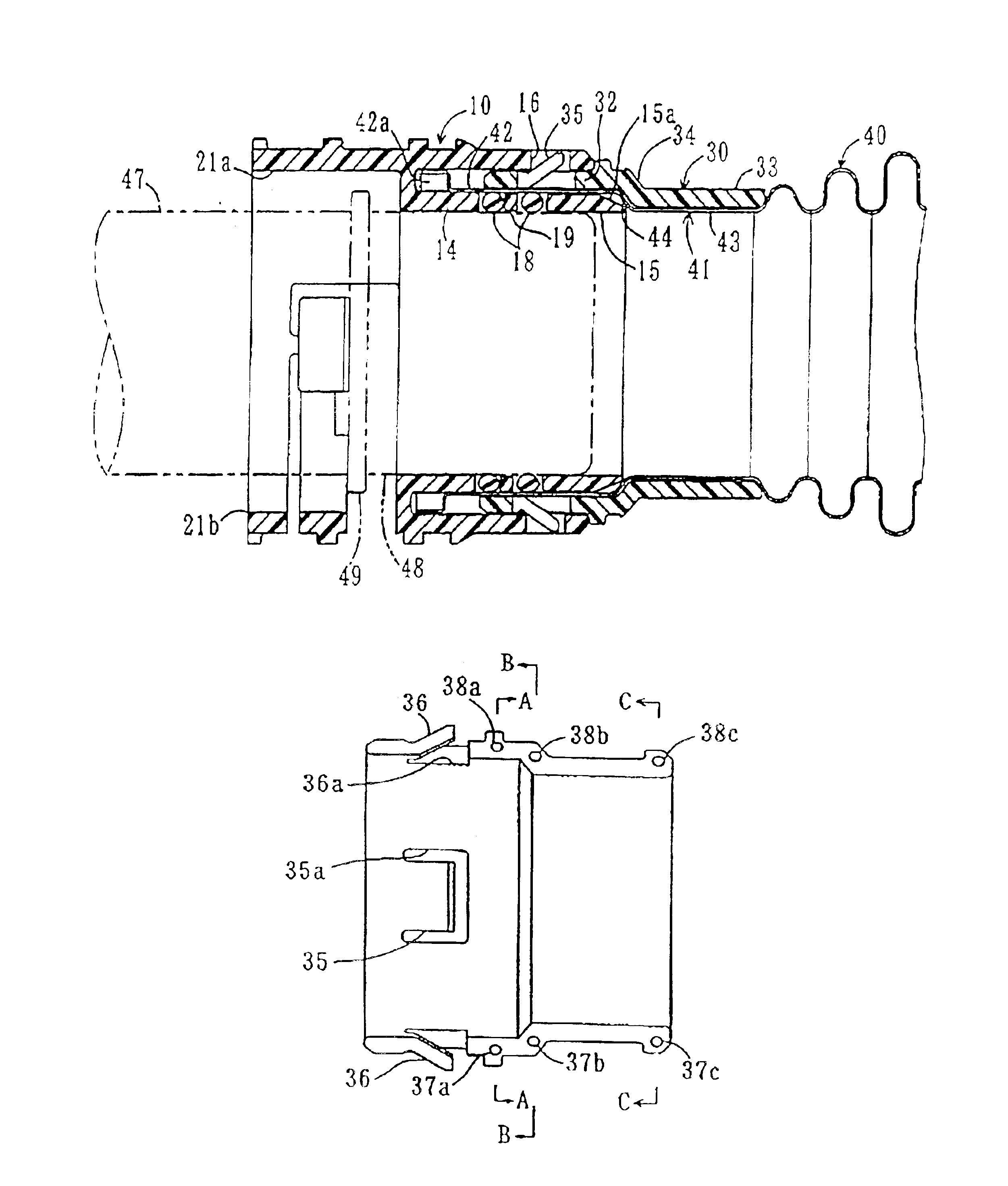
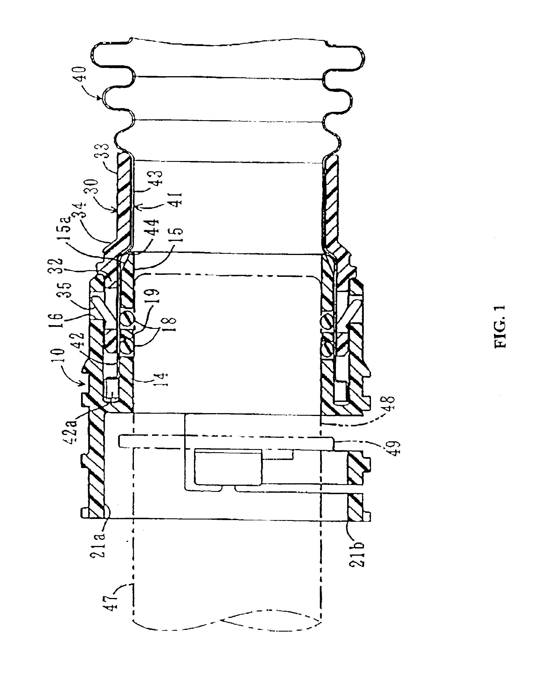
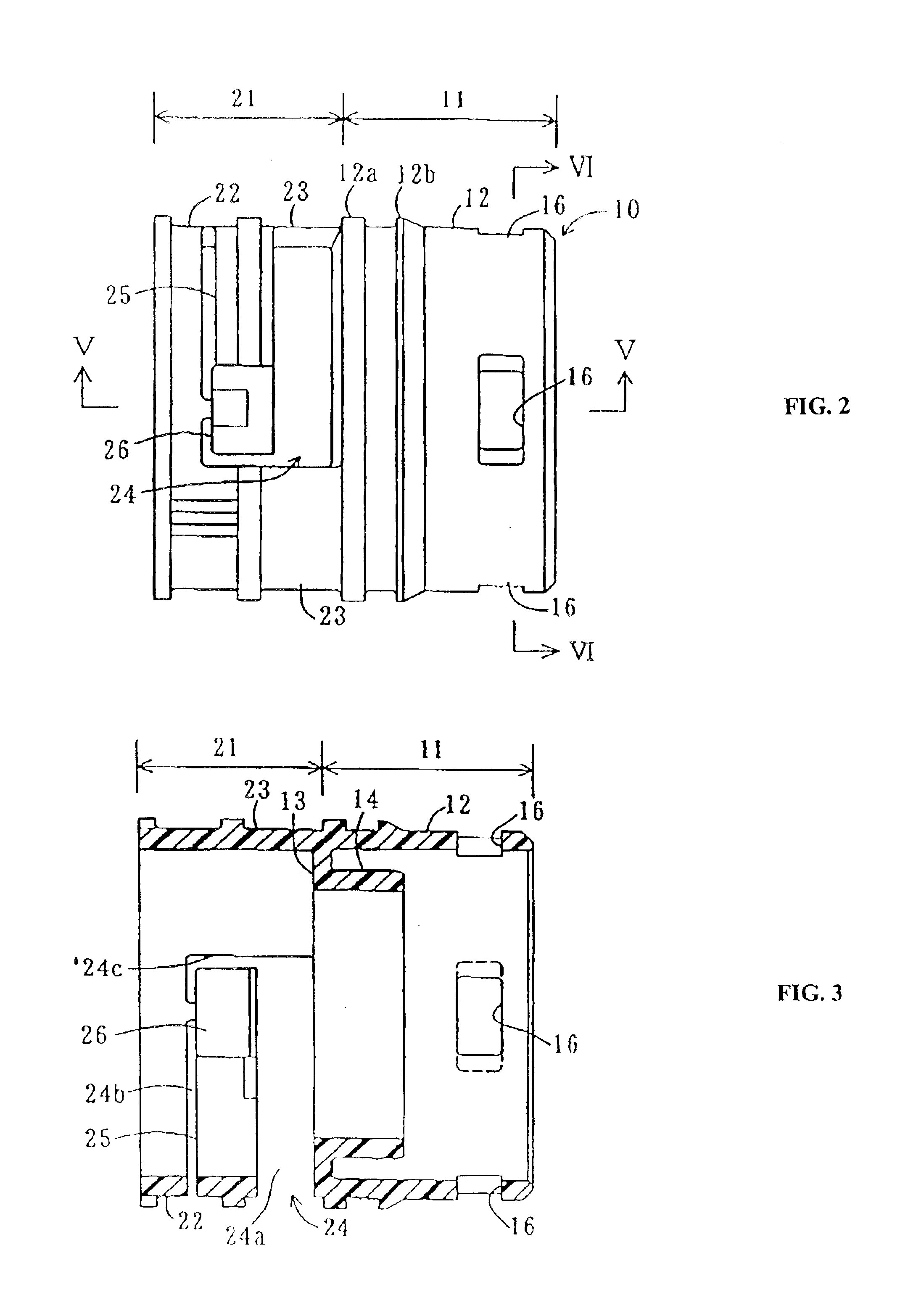
The present invention is described with references to the drawings. FIG. 1 is a front-view cross-section drawing of a tube connecting structure according to the present invention. FIGS. 2 through 10 show simplified views of the connecting member portion of the tube connecting structure. The tube connecting structure includes: a roughly cylindrical connecting member 10 extending axially straight from a first end to a second end; a first tube 40 formed as a resin accordion tube inserted and fitted from the open end at the first end of the connecting member 10; a joining member 30 engaging the first tube 40 to the first end of the connecting member 10; a second tube 47 inserted and fitted into the open end at the second end of the connecting member 10; and an elastic ring-shaped sealing member 19 inserted and fitted into the connecting member 10 and serving to seal a space between the inner perimeter surface of the first tube 40 and the outer perimeter surface of the second tube 47. Wi...


PUM


Abstract

A tube connecting structure is formed with first and second cylindrical sections. The first cylindrical section includes: a joining cylinder with engagement holes disposed at a first end; a ring-shaped flange projecting radially inward from a second end; an inner cylinder extending co-axially toward the first end; and an inner cylindrical member separated axially from the inner cylinder. An O-ring is disposed co-axially between the inner cylinder and inner cylindrical member. Large and small diameter sections of the joining member align with a large-diameter section and small-diameter cylindrical section of the first tube, respectively, and are fitted into the space between the joining cylinder and the inner cylinder and inner cylindrical member. A second tube supported within the second cylindrical section is prevented from slipping out. The O-ring provides a fluid-tight seal between the first and second tubes.

Description

BACKGROUND OF THE INVENTIONThe present invention relates to a tube connecting structure that connects a first tube and a second tube with a connecting member and uses a sealing member to form a fluid-tight seal between an end of the first tube and an end of the second tube.U.S. Pat. No. 6,481,759 presents an example of a conventional tube connecting structure (see FIG. 17). In this tube connecting structure, a main bushing unit 3a of press-in bushing means 3 is pressed into a resin tube 1. The resin tube 1 has a flared end 1a having a large diameter. A joining member 2 is fitted to the outer perimeter of a shoulder 1b of the resin tube 1. Also, a ring-shaped sealing member 4 is mounted in a ring-shaped groove formed by: the outer surface of the flared end 1a of the resin tube 1; a ring-shaped stopper surface means 3b of the press-in bushing means 3; and a cylindrical base section 2a of the joining member 2. An insertion end 5a of a tube-shaped opposing member 5 is relatively fitted ...

Claims


Application Information

Patent Timeline
Patent Type & Authority Patents(United States)
IPC IPC(8): F16L37/098F16L37/00F16L33/00F16L33/28F16L37/12
CPCF16L37/098F16L37/0985Y10S285/921Y10S285/903
Inventor MIYAJIMA, ATSUO
Owner SUMITOMO RIKO CO LTD
Why Eureka
Try Eureka