
Fuse holder component

a fuse holder and component technology, applied in the direction of printed circuit aspects, sustainable manufacturing/processing, final product manufacturing, etc., can solve the problems of difficult surface mounting of fuse holder is not designed to be capable, and the mounter is difficult to surface mount glass-tube fuse on printed board. , to achieve the effect of accurate mounting of the fuse holder component, improving the resistance of solder against separation, and improving the ability of the side pla

Active Publication Date: 2005-01-04
KYOSHIN KOGYO CO LTD
View PDF5 Cites 28 Cited by
  • Summary
  • Abstract
  • Description
  • Claims
  • Application Information

AI Technical Summary

Benefits of technology

The fuse holder component of this invention having the suction surface provided in the suction portion extending from the main body portion of the second side plate is simple in construction and shape, and hence can be easily fabricated, for instance by stamping a metal sheet with improved efficiency in using the metal sheet. Thus, it can be fabricated efficiently at low costs.
Preferably, the second side plate has an engaging portion extending toward the bottom plate from an axially inner edge of the suction portion and adapted to be abutted against an axially outer end face of the glass-tube fuse. This preferred embodiment makes it possible to prevent the glass-tube fuse inserted between the side plates of the fuse holder component from moving outward in the axial direction of the bottom plate. Thus, a fuse holder constituted by a pair of fuse holder components can hold the glass-tube fuse in place, and an electrical contact failure between caps of the glass-tube fuse and the fuse holder can be prevented that is caused by an undesired axial movement of the glass-tube fuse.
Preferably, the first side plate has a first guide portion extending outward in the width direction of the bottom plate from an axially inner half of the main body portion of the first side plate, and the second side plate has a second guide portion extending outward in the width direction of the bottom plate from an axially inner half of the main body portion of the second side plate. This preferred embodiment makes it easy by means of a guiding function of the first and second guide portions to insert a cap of a glass-tube fuse between the first and second side plates of the fuse holder component.
Preferably, a projection is formed in an upper face of a widthwise central part of an axially inner half of the bottom plate. With this preferred embodiment, the main body portions of the first and second side plates cooperate with the projection of the bottom plate to support a cap of a glass-tube fuse by line contact in three places, making it possible to stably support the glass-tube fuse at a location spaced upwardly from a printed board, and to prevent an electrical contact failure between the cap of the glass-tube fuse and the side plates of the fuse holder component.
In soldering the bottom plate of the fuse holder component to a printed board, molten solder adheres to peripheries of the notches formed in the bottom plate so that the surface tension of the molten solder is uniformized in various directions in which the surface tension exerts on the bottom plate. This makes it possible to accurately mount the fuse holder component in position on the printed board, and to improve the resistance of solder against separation caused by tension forces applied thereto in various directions.
Preferably, the first and second side plates include connecting portions curved in transverse section and extending from the side edges of the bottom plate to the main body portions of the side plates, respectively. This preferred embodiment improves the ability of the side plates to hold a glass-tube fuse.

Problems solved by technology

The aforementioned conventional fuse holder is capable of holding a glass-tube fuse and electrically connecting the metal caps of the glass-tube fuse to a patterned surface of a printed board, however, it is not suitable to surface mount a glass-tube fuse on a printed board.
However, the aforementioned conventional fuse holder is not designed to be capable of being picked up by means of a suction nozzle of a mounter., making it difficult for the mounter to surface mount a glass-tube fuse on a printed board.

Method used


Image

  • Fuse holder component
  • Fuse holder component
  • Fuse holder component

Examples


Embodiment Construction

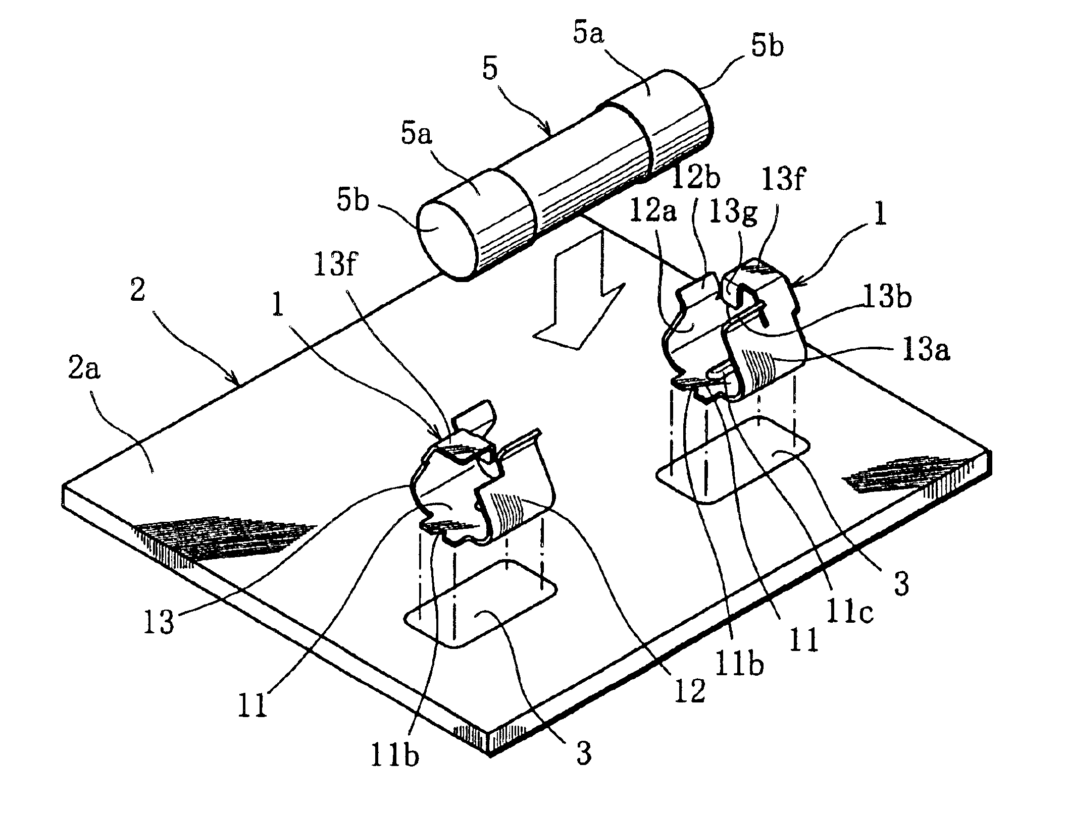
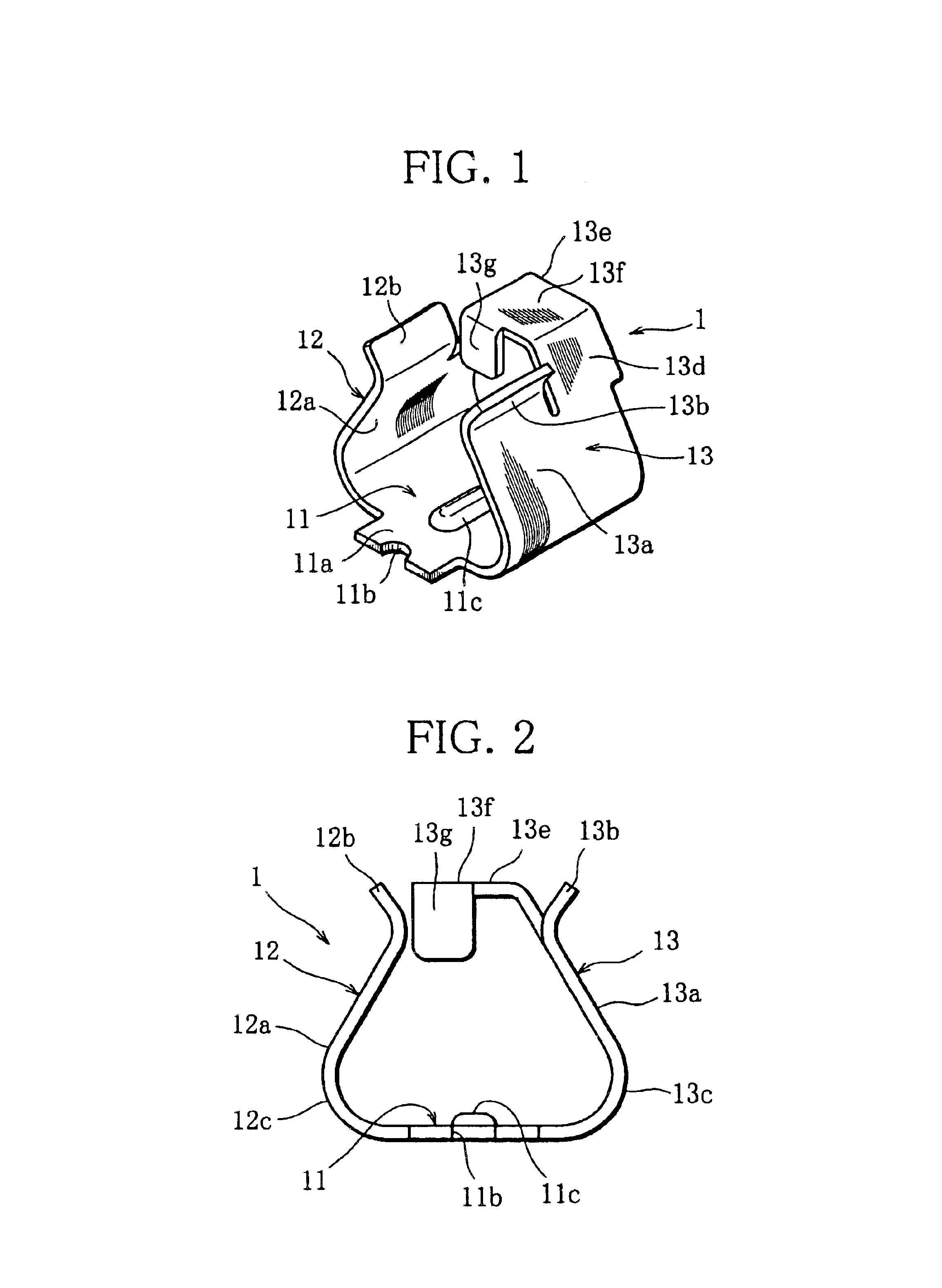
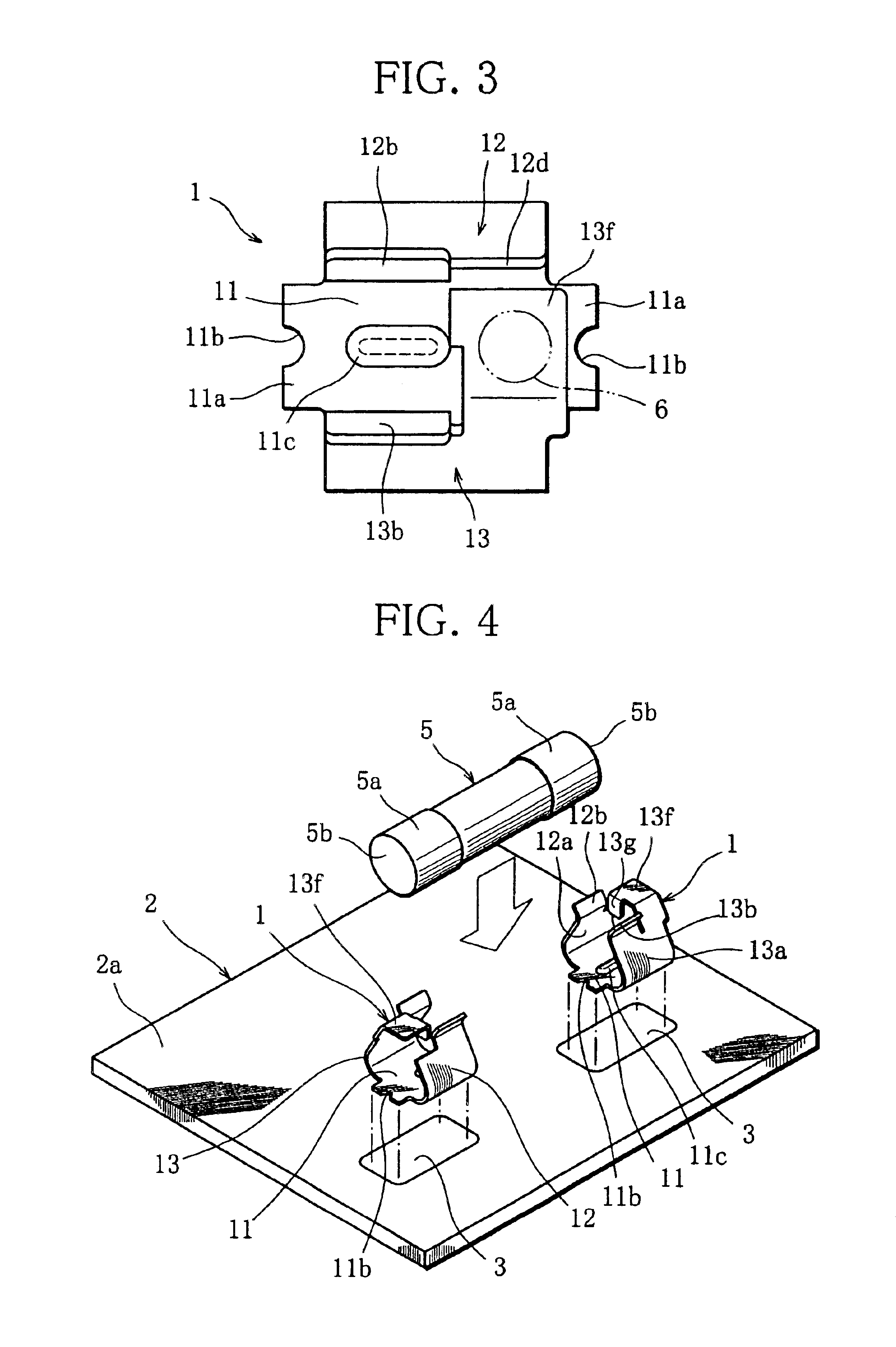
With reference to FIGS. 1-3, a fuse holder component according to an embodiment of this invention will be explained.

The fuse holder component 1 comprises a flat bottom plate 11 and first and second side plates 12, 13 individually extending from side edges of the bottom plate 11, and is formed as a whole into an inverted Ω shape as viewed from front.

The first side plate 12 comprises a connecting portion 12c extending from one side edge of the bottom plate 11 and curved in circular arc in transverse section, a main body portion 12 obliquely extending from the connecting portion 12c upward and inward in the width direction of the bottom plate, and a first guide portion 12b extending from an axially inner half of the main body portion 12a outward in the width direction of the bottom plate. Similarly, the second side plate 13 includes a connecting portion 13c extending from another side edge of the bottom plate 11 and curved in circular arc, a main body portion 13a obliquely extending fr...


PUM


Abstract

A fuse holder component includes a bottom plate fixed to a printed board, and first and second side plates whose main body portions individually extend from side edges of the bottom plate. The second side plate includes a suction portion extending through an extension portion from the main body portion and provided with a suction surface to which a suction nozzle of a mounter is accessible. A pair of fuse holder components, surface-mounted on the printed board by using the mounter, constitute a fuse holder that stably holds a glass-tube fuse.

Description

BACKGROUND OF THE INVENTION1. Technical FieldThe present invention relates to a fuse holder for holding a glass-tube fuse, and more particularly, to a component of a fuse holder suitable for surface mount of a glass-tube fuse on a printed board.2. Related ArtA fuse holder used to mount a glass-tube fuse on a printed board comprises a pair of holder fitments made of metal, as disclosed for instance in Japanese provisional utility model publication no. 49-151262. Each holder fitment includes a leg portion and a pair of arm portions formed integrally therewith. The holder fitments are disposed at a distance from each other on a printed board, with their leg portions inserted into mounting holes formed in the printed board, and are soldered at the leg portions to a patterned surface of the printed board. Each holder fitment is further provided with an auxiliary arm portion that cooperates with the arm portions to three-point support a corresponding one of metal caps of the glass-tube fu...

Claims


Application Information

Patent Timeline
IPC IPC(8): H01R43/20H01R4/48H01H85/20H05K3/30H05K3/34
CPCH01H85/202H01R4/4809H01R43/205H05K3/301H01H2085/2085H05K2201/1084H05K3/341H05K2201/10181H05K2201/1031H05K2201/10583Y02P70/50
Inventor KITAJIMA, YOSHIKAZUNISHIMURA, IWAOITO, KOJI
Owner KYOSHIN KOGYO CO LTD
Learn More