Digital fractional phase detector
a detector and digital technology, applied in the field of digital fractional phase detectors, can solve the problems of frequency synthesizers that do not take advantage of recently developed high-density digital gate technology, analog-intensive circuitry that does not work very well, and analog-intensive circuitry
- Summary
- Abstract
- Description
- Claims
- Application Information
AI Technical Summary
Benefits of technology
Problems solved by technology
Method used
Image
Examples
first embodiment
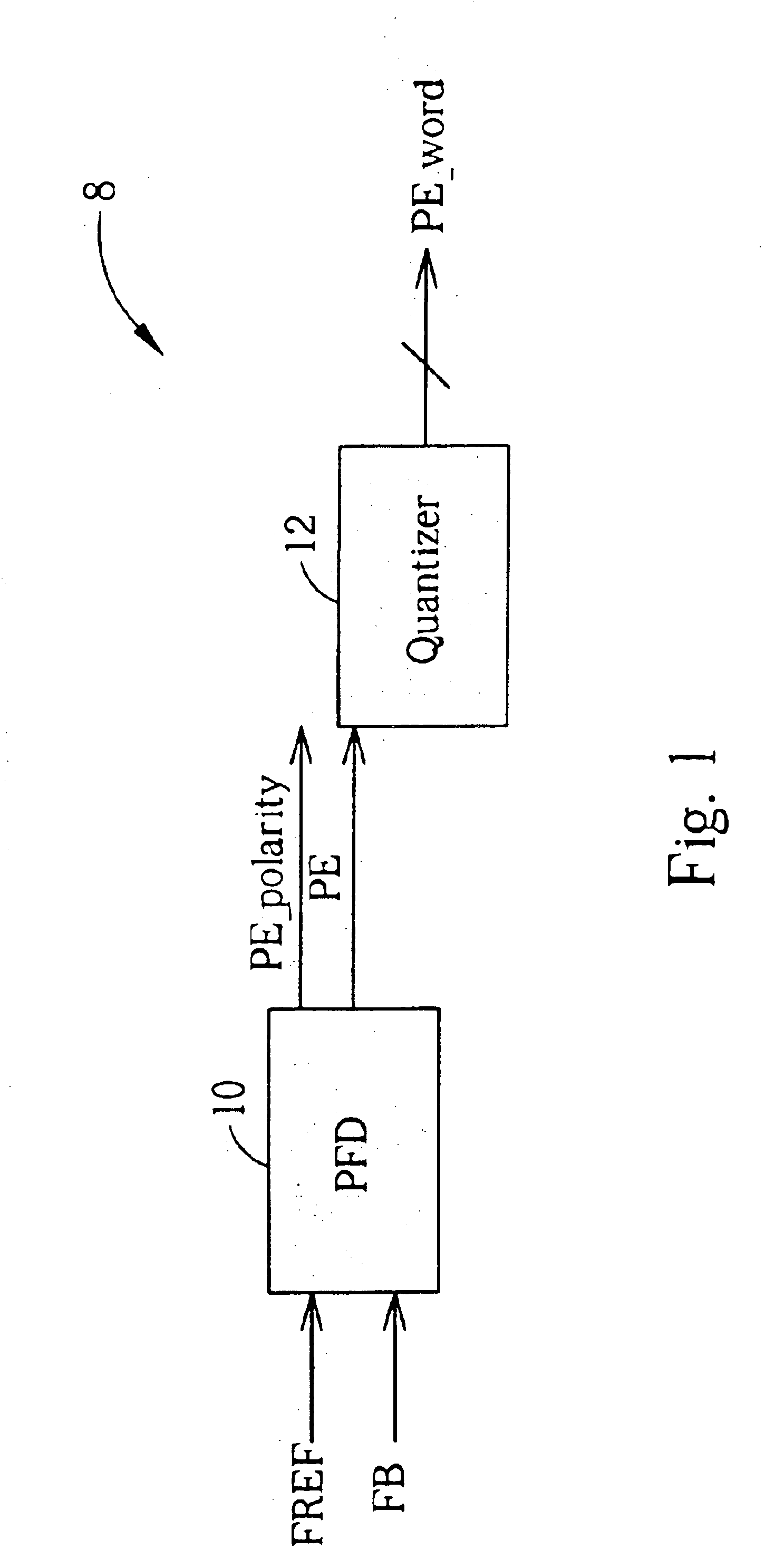
FIG. 1 shows a digital fractional phase detector 8 according to the present invention. The digital fractional / phase detector 8 has a phase / frequency detector (PFD) 10, which outputs a phase error signal PE and a PE-polarity signal according to the phase difference between a reference clock signal FREF and a feedback clock signal FB, and a quantizer 12 connected to the phase / frequency detector (PFD) 10. The pulse width of the phase error signal PE corresponds to the phase difference between the reference clock signal FREF and the feedback clock signal FB and the polarity of the PE-polarity signal is for determining whether the feedback clock signal FB is leading (or lagging) the reference clock signal FREF. The quantizer 12 measures the pulse width of the phase error signal PE and outputs a digital pulse width value PE_word according to the measurement.
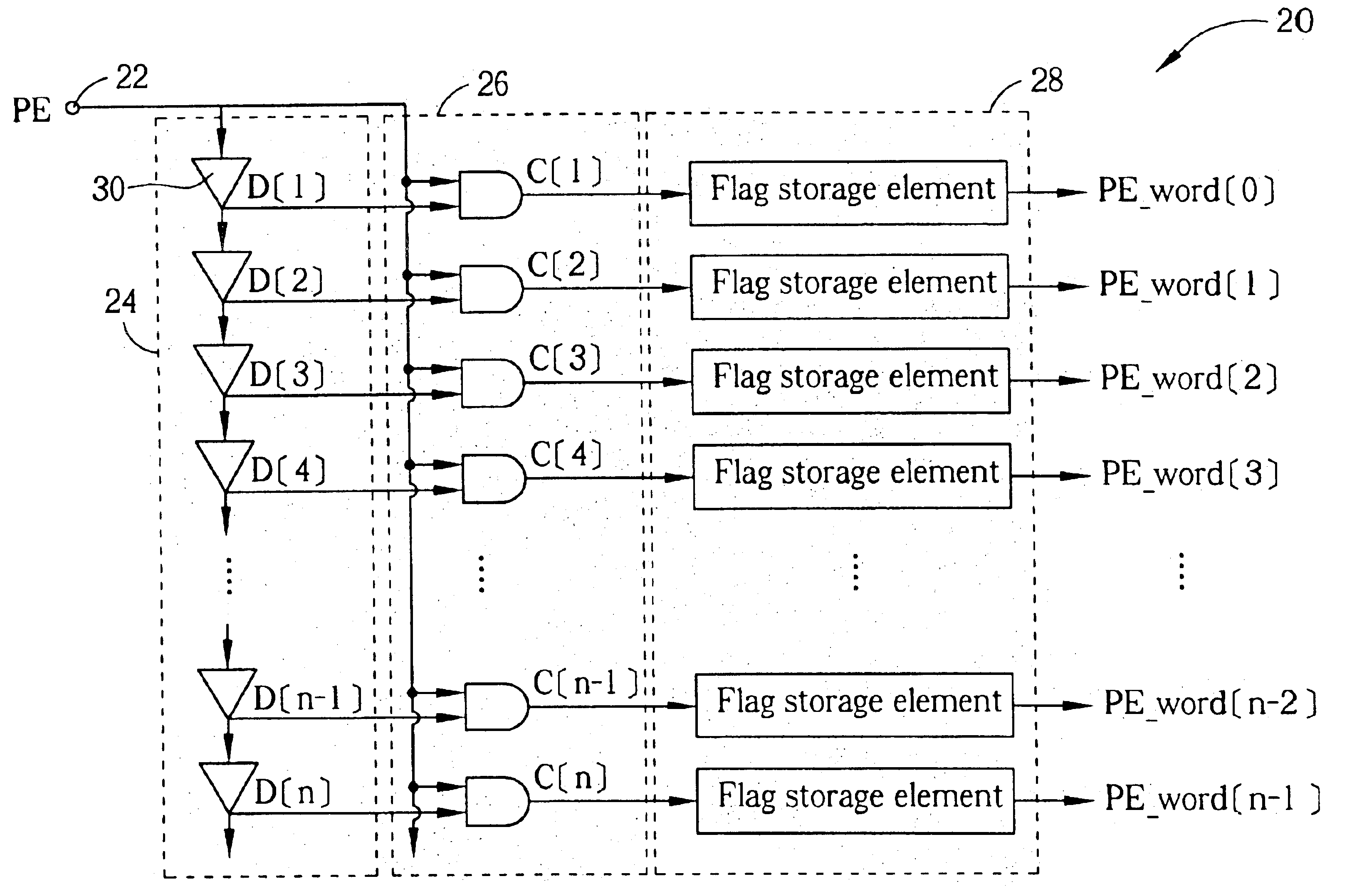
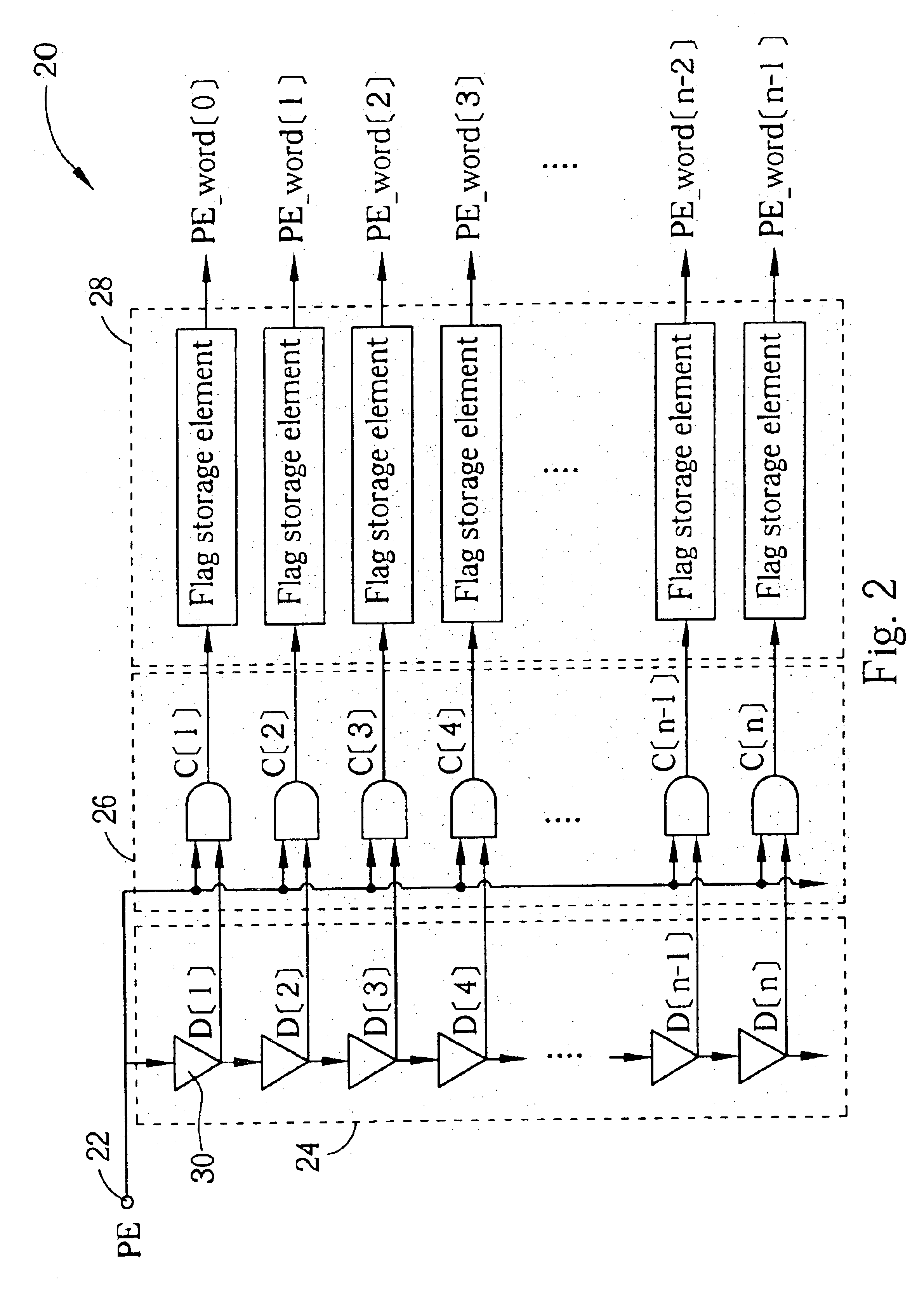
FIG. 2 shows a gate-level diagram of a quantizer 20 that is an embodiment of the quantizer 12 shown in FIG. 1. In this implementation...
second embodiment
FIG. 4 shows a gate-level diagram of the quantizer 32. In this implementation the quantizer 32 comprises a phase error input terminal 34, a compensator circuit 38, a plurality of delay elements 36, a plurality of even comparator elements 40, a plurality of odd comparator elements 42, and a plurality of flag storage elements 44. The compensator circuit 38 has a first output terminal for outputting a compensated phase error signal PECOMP and a second output terminal for outputting an inverted phase error signal PEINVERT according to phase error signal PE. The compensated phase error signal PECOMP is delayed by the same amount of time that the inverted phase error signal PEINVERT is delayed due to being inverted. As shown in FIG. 5 an inverter 46 connected in series with a transmission gate 48 can be used to generate the inverted phase error signal PEINVERT and two inverters 50, 52 connected in series can be used to generate the compensated phase error signal PECOMP.
The compensated pha...
PUM
 Abstract
Description
Claims
Application Information
 - R&D
- Intellectual Property
- Life Sciences
- Materials
- Tech Scout
- Unparalleled Data Quality
- Higher Quality Content
- 60% Fewer Hallucinations
Browse by: Latest US Patents, China's latest patents, Technical Efficacy Thesaurus, Application Domain, Technology Topic, Popular Technical Reports.
© 2025 PatSnap. All rights reserved.Legal|Privacy policy|Modern Slavery Act Transparency Statement|Sitemap|About US| Contact US: help@patsnap.com


