Digital fractional phase detector

a detector and digital technology, applied in the field of digital fractional phase detectors, can solve the problems of frequency synthesizers that do not take advantage of recently developed high-density digital gate technology, analog-intensive circuitry that does not work very well, and analog-intensive circuitry

Inactive Publication Date: 2005-01-06
REALTEK SEMICON CORP
View PDF6 Cites 8 Cited by
  • Summary
  • Abstract
  • Description
  • Claims
  • Application Information

AI Technical Summary

Benefits of technology

[0011] It is an advantage of the present invention digital fraction phase detector that no over-sampling clock is needed.
[0012] It is a further advantage of the claimed invention digital fractional phase detector that the quantizer directly measures the pulse width of the phase error signal output from the phase error detector.
[0013] These and other objectives of the claimed invention will no doubt become obvious to those of ordinary skill in the art after reading the following detailed description of the preferred embodiment that is illustrated in the various figures and drawings.

Problems solved by technology

Conventional RF frequency synthesizer architectures are analog-intensive and generally require a low loop bandwidth to reduce the familiar and well-known reference or compare frequency spurs.
The conventional PLL-based frequency synthesizers generally comprise analog-intensive circuitry that does not work very well in a low voltage constrained high-speed CMOS environment.
Such frequency synthesizers do not take advantage of recently developed high-density digital gate technology.
Such architectures cannot be used at RF frequencies.
However, because the VCO output clock and the reference clock are not synchronous signals with respect to each other, quantization resolution and accuracy is not optimal.

Method used


Image

  • Digital fractional phase detector
  • Digital fractional phase detector
  • Digital fractional phase detector

Examples


first embodiment

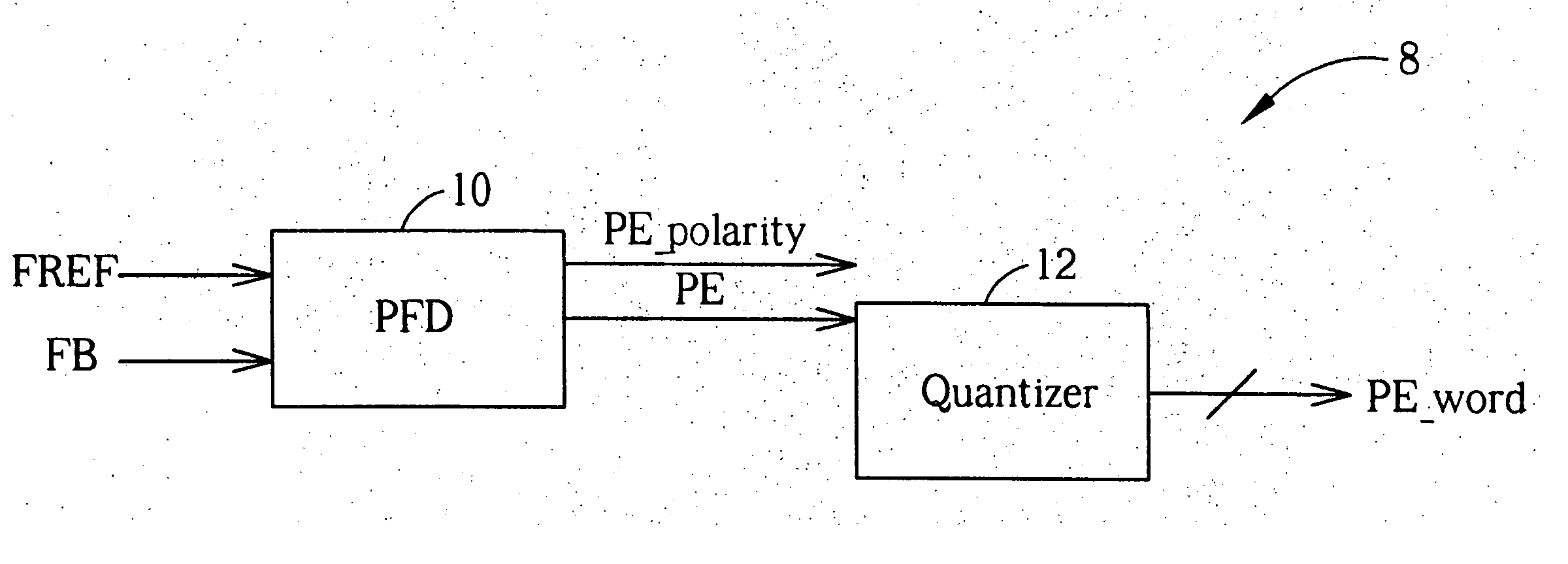
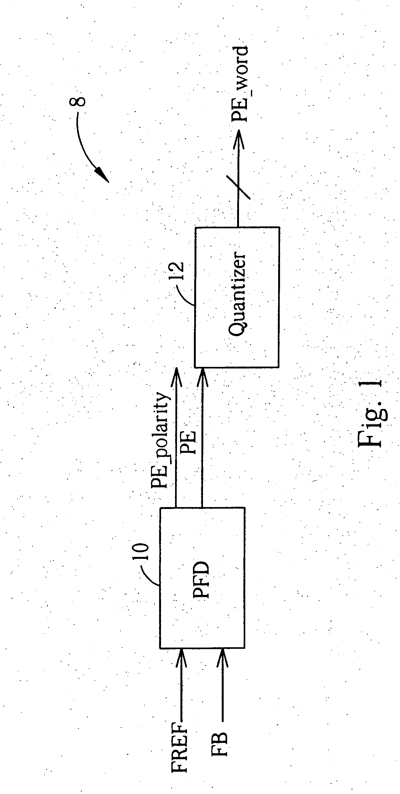
[0021]FIG. 1 shows a digital fractional phase detector 8 according to the present invention. The digital fractional phase detector 8 has a phase / frequency detector (PFD) 10, which outputs a phase error signal PE and a PE-polarity signal according to the phase difference between a reference clock signal FREF and a feedback clock signal FB, and a quantizer 12 connected to the phase / frequency detector (PFD) 10. The pulse width of the phase error signal PE corresponds to the phase difference between the reference clock signal FREF and the feedback clock signal FB and the polarity of the PE-polarity signal is for determining whether the feedback clock signal FB is leading (or lagging) the reference clock signal FREF. The quantizer 12 measures the pulse width of the phase error signal PE and outputs a digital pulse width value PE_word according to the measurement.

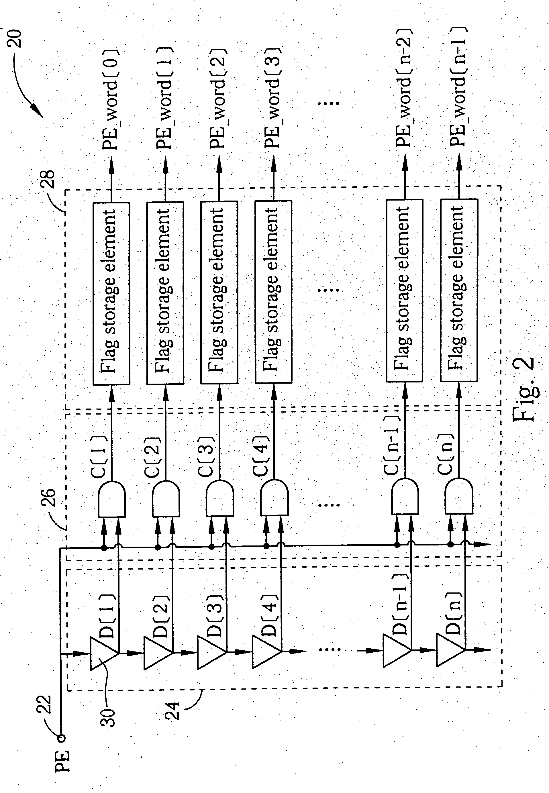
[0022]FIG. 2 shows a gate-level diagram of a quantizer 20 that is an embodiment of the quantizer 12 shown in FIG. 1. In this im...

second embodiment

[0024]FIG. 4 shows a gate-level diagram of the quantizer 32. In this implementation the quantizer 32 comprises a phase error input terminal 34, a compensator circuit 38, a plurality of delay elements 36, a plurality of even comparator elements 40, a plurality of odd comparator elements 42, and a plurality of flag storage elements 44. The compensator circuit 38 has a first output terminal for outputting a compensated phase error signal PECOMP and a second output terminal for outputting an inverted phase error signal PEINVERT according to phase error signal PE. The compensated phase error signal PECOMP is delayed by the same amount of time that the inverted phase error signal PEINVERT is delayed due to being inverted. As shown in FIG. 5 an inverter 46 connected in series with a transmission gate 48 can be used to generate the inverted phase error signal PEINVERT and two inverters 50, 52 connected in series can be used to generate the compensated phase error signal PECOMP.

[0025] The co...


PUM


Abstract

A digital fractional phase detector is shown that uses a phase error detector for generating a phase error signal based on the phase difference between a reference clock signal and a feedback clock signal. A quantizer directly measures the pulse width of a phase error signal and outputs the value in a digital form. By directly measuring the phase error signal, quantization accuracy is increased. In order to calibrate the digital fractional phase detector, a calibration pulse generator generates a calibration pulse of a known duration and passes it to the quantizer.

Description

BACKGROUND OF INVENTION [0001] 1. Field of the Invention [0002] The invention relates to a digital fractional phase detector, and more particularly, to a digital fractional phase detector for use in a digital frequency synthesizer. [0003] 2. Description of the Prior Art [0004] Frequency synthesizers using analog circuit techniques are well known in the art. Conventional RF frequency synthesizer architectures are analog-intensive and generally require a low loop bandwidth to reduce the familiar and well-known reference or compare frequency spurs. [0005] The conventional PLL-based frequency synthesizers generally comprise analog-intensive circuitry that does not work very well in a low voltage constrained high-speed CMOS environment. Such frequency synthesizers do not take advantage of recently developed high-density digital gate technology. [0006] Newer frequency synthesizer architectures have used sigma-delta modulated frequency divider techniques to randomize the above discussed fr...

Claims


Application Information

Patent Timeline
Patent Type & Authority Applications(United States)
IPC IPC(8): H03D13/00
CPCH03D13/003
Inventor CHOU, YU-PIN
Owner REALTEK SEMICON CORP
Why Eureka
Try Eureka