Image reconstruction method for computed tomography

Active Publication Date: 2005-01-04
SIEMENS HEALTHCARE GMBH
View PDF4 Cites 12 Cited by
  • Summary
  • Abstract
  • Description
  • Claims
  • Application Information

AI Technical Summary

Benefits of technology

An embodiment of the present invention is based on an object of specifying a method for permitting an image quality to be enhanced.
Accordingly, the filtering is carried out in the direction of the tangent to the focal path belonging to the respective focal position. Furthermore, the normalization is carried out in a voxel-specific manner, in particular for each voxel considered. It has been shown that, by way of the combination of this filtering according to the invention and the voxel-specific normalization, a particularly high image quality can be achieved. It is particularly advantageous if filtering is carried out in the aforementioned filter direction. The filter direction in this case corresponds to the direction of the projection of the spiral tangent onto the detector, the projection direction of course being determined by the connecting line from the focus to the center of rotation of the gantry.
The selection of this filter direction is based on the finding that the 2D method, which permits a high image quality and is based on preliminary images, would change into a 3D method if the sections of the focal path on which the calculation of preliminary images is based were to be shortened to such a great extent that it would still only cover a single projection, of which the data would then be filtered in the direction of the tangent to the focal path. Therefore, it would then be possible to expect such a 3D method would then permit a comparably good image quality to that of the 2D method.
Furthermore, as a result of the normalization for each voxel considered, care is taken at the same time that voxel-specific image artifacts, which could be produced by possible multiple strikes of rays of a voxel, are avoided.
is formed. This procedure permits an image quality which is improved again, since possible overemphasis of voxels which are struck by more rays than other voxels is eliminated, and therefore corresponding artifacts are avoided. The CT value of the respective voxel is obtained by way of summation over θ.
The method according to an embodiment of the present invention may be used, for example, when according to one variant of the invention, the focal path is a circular path (tomogram scanning). According to a preferred variant of the present invention, the focal path is a spiral path, which is brought about by the focus being moved on a circular path about the system axis and, at the same time, there being a relative movement, between focus and object to be examined, in the direction of the system axis. On the basis of such spiral scanning, even relatively large volumes of the object to be examined can be examined without difficulty.

Problems solved by technology

Computed tomography methods of the indicated type are known under the term “filtered backprojection.” However, as 3D methods, that is to say in conjunction with a matrix-like detector array, known methods do not provide an image quality which is judged to be adequate in practice.
This is because “cone beam artifacts” occur due to the use of the conical X-ray beam.
Additionally disadvantageous in these methods is that redundant data are not used, such as data produced during spiral scanning with a small table advance as a result of multiple irradiation of one and the same voxel, which results in the incomplete use of an imaging radiation dose administered to the object.
These 2D methods are less useful for detector arrays with a large width.
That is, in the direction of the system axis, since then an extremely large number of preliminary images have to be processed, which is a problem even when there is a large amount of computing power available.

Method used


Image

  • Image reconstruction method for computed tomography
  • Image reconstruction method for computed tomography
  • Image reconstruction method for computed tomography

Examples


Embodiment Construction

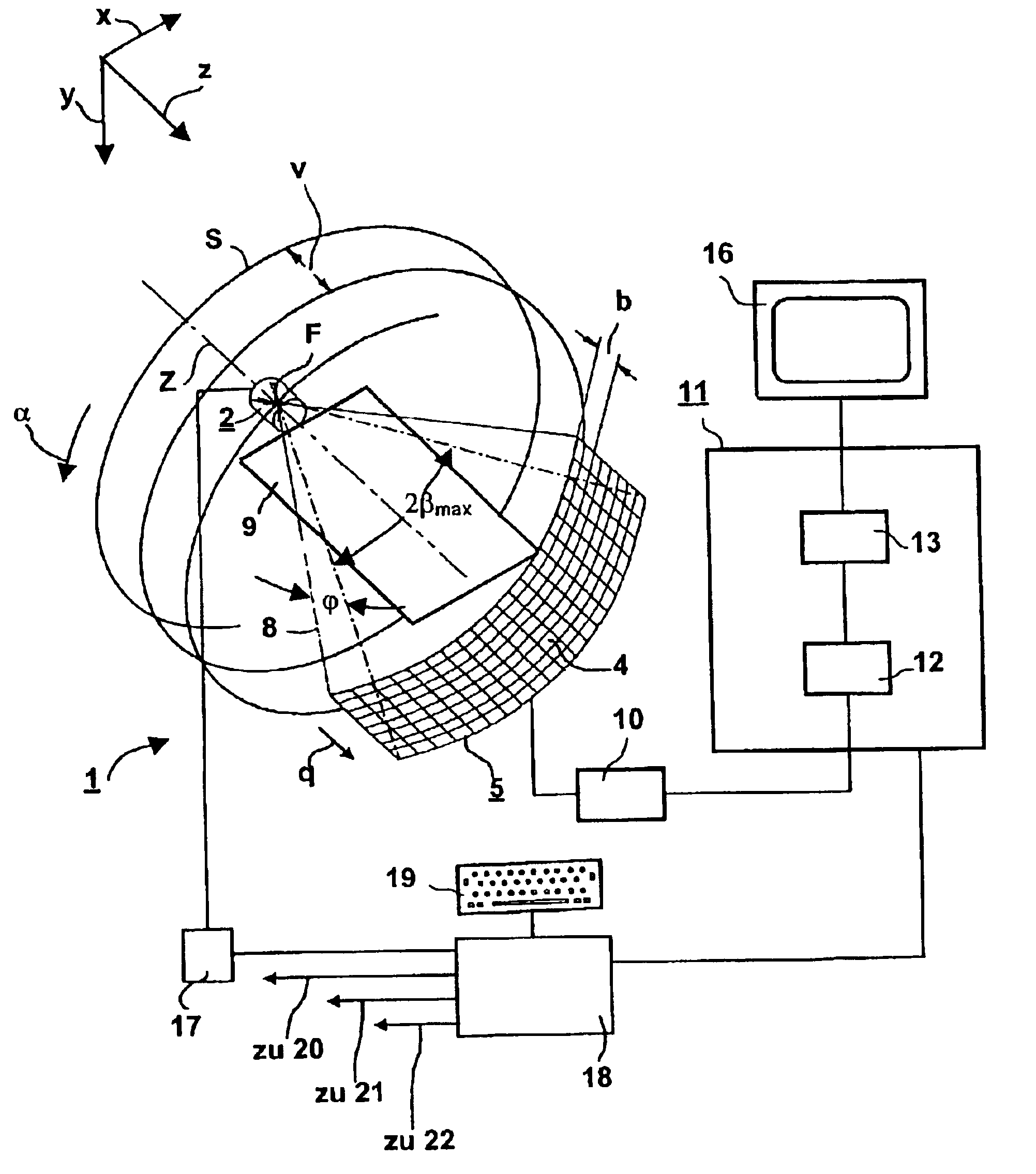
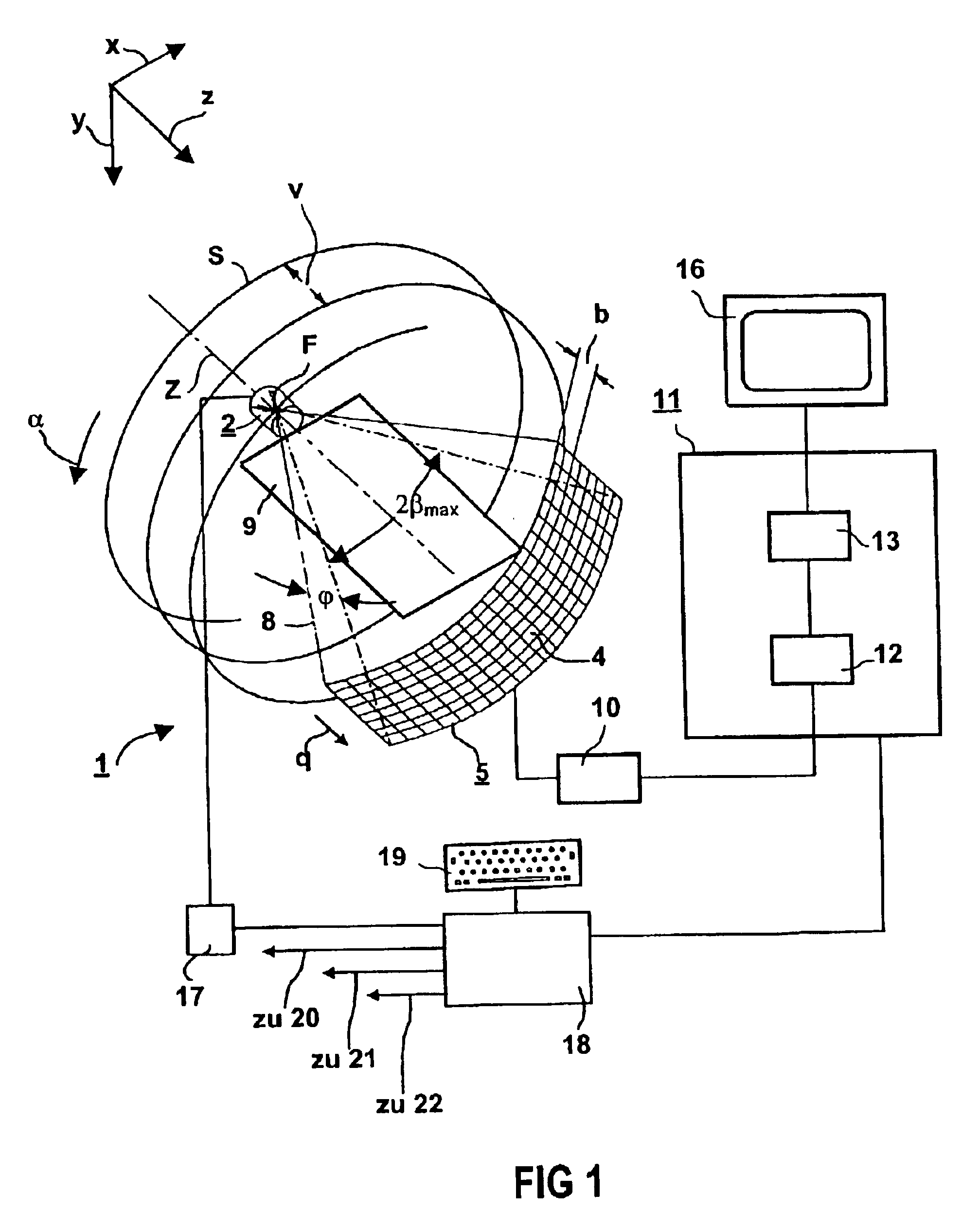
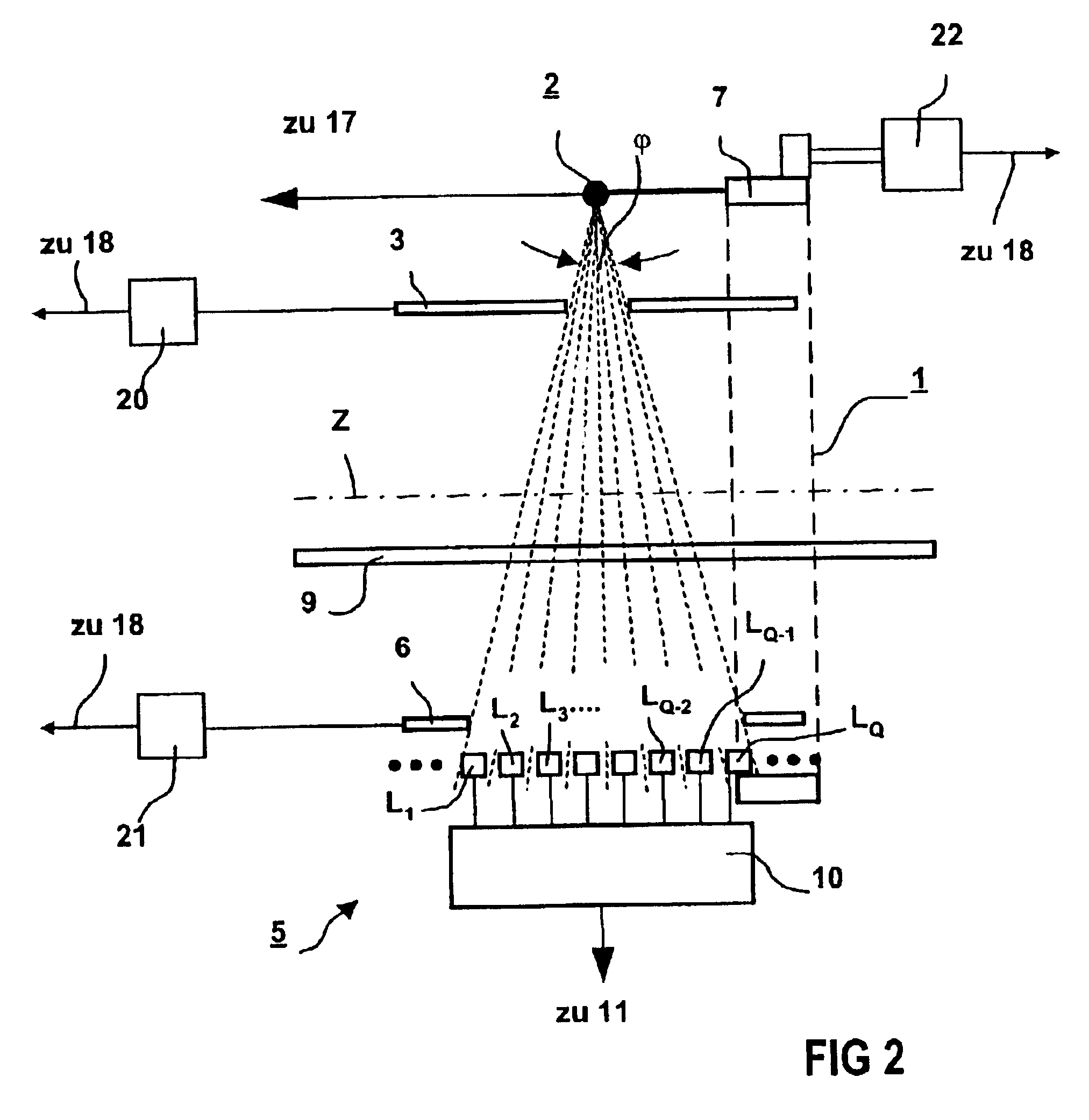
FIGS. 1 and 2 illustrate a third generation computed tomography (CT) device, which is suitable for carrying out a method according to an embodiment of the present invention. A measuring arrangement of the CT device, designated overall by 1, has an X-ray source, designated overall by 2, with a radiation aperture 3 (FIG. 2) placed in front of it and close to the source, and a detector system 5 constructed as a two-dimensional array of a plurality of lines and columns of detector elements—one of these is designated by 4 in FIG. 1—with a radiation aperture 6 (FIG. 2) placed in front thereof and close to the detector. In FIG. 1, for reasons of clarity, only eight lines of detector elements 4 are illustrated, but the detector system 5 has further lines of detector elements 4, which is indicated by dots in FIG. 2.

As is illustrated in FIG. 2, the X-ray source 2 with the radiation aperture 3, on the one hand, and the detector system 5 with the radiation aperture 6, on the other hand, are fit...


PUM


Abstract

A method for computed tomography, includes, in order to scan an object to be examined with a conical beam originating from a focus and with a matrix-like detector array for detecting the beam, the focus is moved, relative to the object to be examined, on a focal path around a system axis. A detector array supplies an output data corresponding to received radiation. The output data is filtered, and the filtered output data is backprojected three-dimensionally in order to produce at least one slice of a layer of the, which has a layer thickness. The slice represents absorption values obtained from the output data of a voxel belonging to the layer for the radiation from the beam. Filtering is carried out at least also in the direction of the tangent to the focal path belonging to a respective focal position, and normalization is carried out for each voxel considered.

Description

The present application hereby claims priority under 35 U.S.C. §119 on German patent application number 10159927.7 filed Dec. 6, 2001, the entire contents of which are hereby incorporated herein by reference.FIELD OF THE INVENTIONThe present invention generally relates to an image reconstruction method for computed tomography.BACKGROUND OF THE INVENTIONCurrent computed tomography systems scan an object to be examined with a conical beam originating from a focus and with a matrix-like detector array. A detector array supplies output data corresponding to a received radiation in the form of rays having a particular ray geometry.The output data is filtered and then back-projected three-dimensionally in order to produce at least one slice of a layer of an object for examination.Computed tomography methods of the indicated type are known under the term “filtered backprojection.” However, as 3D methods, that is to say in conjunction with a matrix-like detector array, known methods do not ...

Claims


Application Information

Patent Timeline
IPC IPC(8): G06T17/00A61B6/03G06T1/00
CPCG06T17/00A61B6/027Y10S378/901
Inventor BRUDER, HERBERTFLOHR, THOMASSTIERSTORFER, KARL
Owner SIEMENS HEALTHCARE GMBH
Why Eureka
Try Eureka