
Fuel heater

Inactive Publication Date: 2005-01-04
CSXT INTPROP CORP
View PDF15 Cites 35 Cited by
  • Summary
  • Abstract
  • Description
  • Claims
  • Application Information

AI Technical Summary

Benefits of technology

In accordance with various embodiments herein, fuel consumption is not adversely affected by heating of fuel in the tank. On the contrary, fuel consumption and concomitant emissions are improved. In addition, no separate heating fluid is needed to effectuate fuel heating.
In various embodiments, the temperature of fuel adjacent to the fuel suction intake of a fuel heater is maintained above the cloud point temperature. The temperature of fuel surrounding the fuel heater may be similarly maintained. Thus, waxing of fuel in a fuel tank may be prevented.

Problems solved by technology

In diesel fuel powered transportation environments, extremely cold temperatures adversely affect diesel engine operation.
Generally, large diesel engines, such as locomotive engines, are not shut down during cold weather conditions due to the difficulty in restarting such engines.
Diesel engines do not have the benefit of an electrical spark to generate combustion and must rely on heat generated by compressing air in order to ignite fuel in the engine cylinders.
Additionally, diesel fuel tends to exhibit poor viscous qualities at low temperatures.
Moreover, in extremes of cold, diesel fuel tends to gel, thus making engine operation difficult.
When locomotives are operated in cold climates, high viscosity and wax clouding of the cold diesel fuel tend to clog fuel filters and fuel injection nozzles.
Fuels with low viscosity may not provide sufficient lubrication for the precision fit of fuel injection pumps or injector plungers, resulting in leakage or increased wear.
Fuels that do not meet viscosity requirements can lead to performance complaints.
Diesel fuels with high viscosity tend to form larger droplets on injection, which can cause poor combustion and increased exhaust smoke and emissions.
Such wax fractions tend to more readily crystallize out in engine parts and fuel lines, making engine starting and operating even more difficult.
Existing fuel heaters are complex, unwieldy, and not optimally effective.

Method used


Image

  • Fuel heater
  • Fuel heater
  • Fuel heater

Examples


Embodiment Construction

Embodiments of the present invention provide for an automatic fuel heater and associated methods.

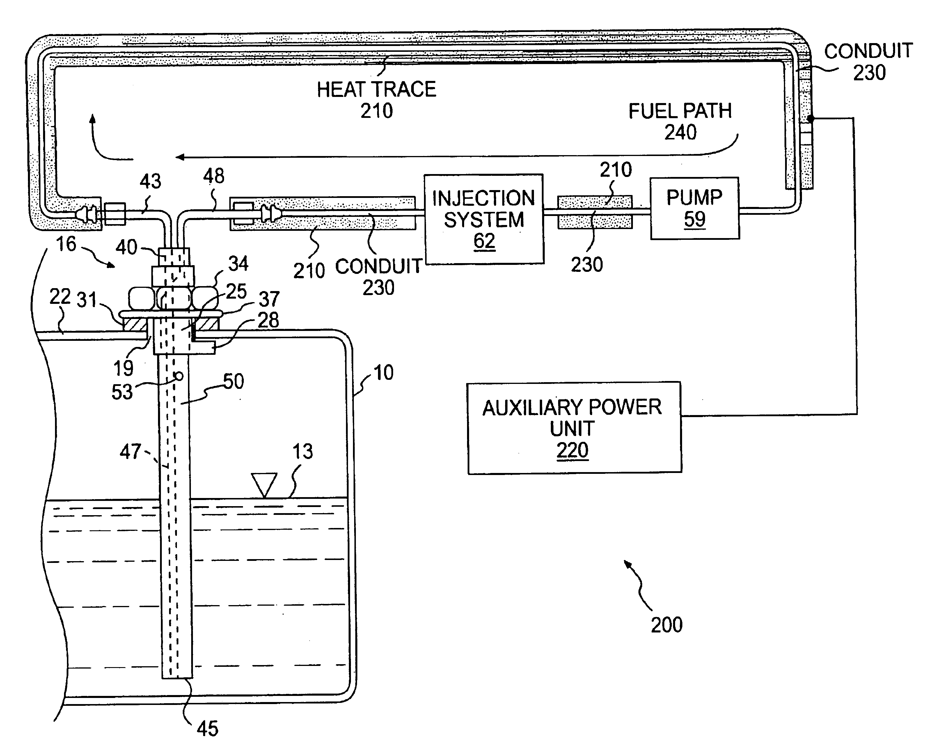
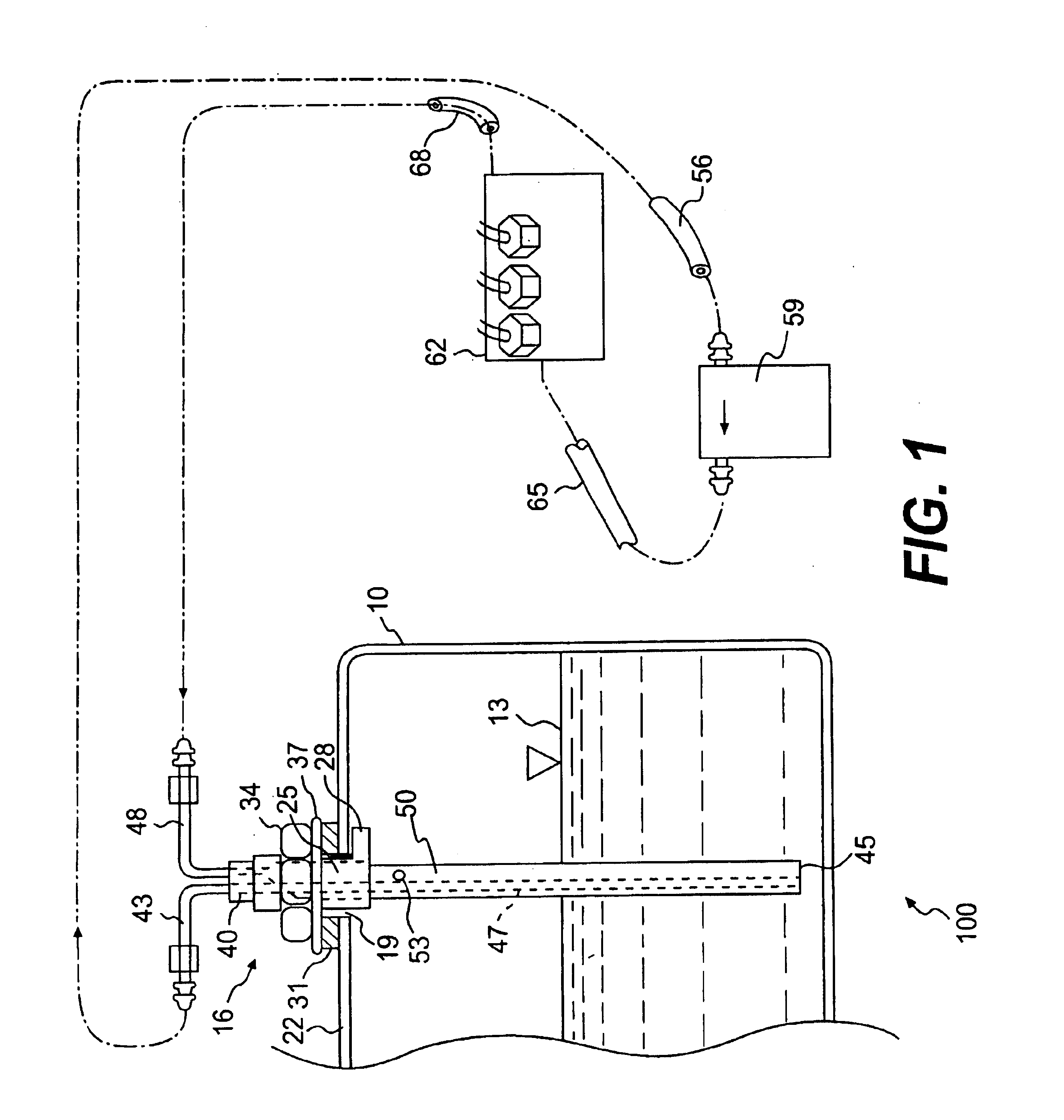
In one embodiment, a fuel heater includes an elongated member that fits through an opening in a fuel tank. The elongated member includes a fuel suction channel and a return channel. Fuel is drawn from the tank, warmed, and returned to the tank.

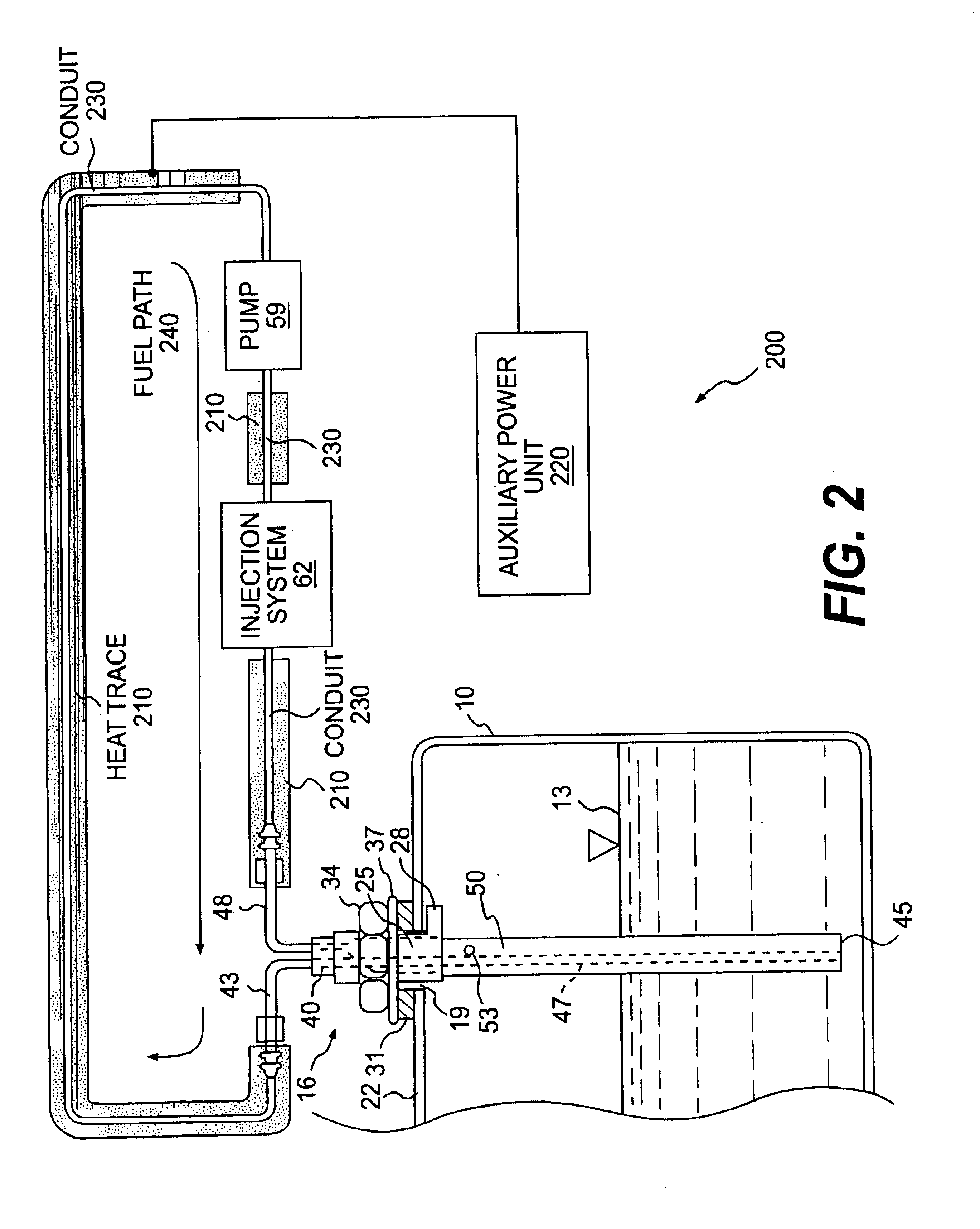
In an embodiment, the elongated member includes a first tube, a second tube, and a third tube. The first tube defines a fuel channel and ends with a bottom fuel intake. Fuel may be drawn from the tank and conveyed by a supply side line coupled to the first tube. The second tube is coupled to a return side line that conveys warmed fuel back to the tank. The third tube substantially coaxially surrounds the first tube, and an outlet of the second tube enters the third tube.

In other embodiments, a heat trace may be employed to heat fuel drawn from, and returning to, the tank. The heat trace may be powered by a power source, such as an auxiliary power u...


PUM


Abstract

A fuel heater for a tank includes an elongated member that fits through an opening in the tank. The elongated member includes a first tube that defines a fuel channel and ends with a bottom fuel intake. Fuel may be drawn from the tank and conveyed by a supply side line coupled to the first tube. A second tube of the elongated member is coupled to a return side line that conveys warmed fuel back to the tank. A third tube substantially coaxially surrounds the first tube, and an outlet of the second tube enters the third tube. A heat trace may be employed to warm the fuel. Accordingly, the temperature of fuel in the tank may be maintained above the cloud point temperature.

Description

BACKGROUND1. FieldEmbodiments of the present invention relate to heat exchangers.2. Description of Related ArtIn diesel fuel powered transportation environments, extremely cold temperatures adversely affect diesel engine operation. Generally, large diesel engines, such as locomotive engines, are not shut down during cold weather conditions due to the difficulty in restarting such engines. Diesel engines do not have the benefit of an electrical spark to generate combustion and must rely on heat generated by compressing air in order to ignite fuel in the engine cylinders.In low temperature conditions (ambient temperatures below about 40° F., for example), various factors contribute to the difficulty in starting a diesel engine. For instance, cold ambient air drawn into the engine must be increased in temperature sufficiently to cause combustion. Additionally, diesel fuel tends to exhibit poor viscous qualities at low temperatures. Moreover, in extremes of cold, diesel fuel tends to ge...

Claims


Application Information

Patent Timeline
IPC IPC(8): B60L1/00B60L1/02F24H1/10F24H1/22F24H1/34
CPCF02M31/125F02M37/0017F02M37/0052F02M37/0076F02M37/0058F02B3/06Y02T10/126Y02T10/12
Inventor BIESS, LAWRENCE J.GOTMALM, CHRISTER T.
Owner CSXT INTPROP CORP
Learn More