Memory-block coalescing based on run-time demand monitoring

a technology of run-time demand and memory block, applied in the field of computer memory allocators, can solve the problems of large quantity of intermediates, large number of smaller blocks, and insufficient number of smaller blocks later

Inactive Publication Date: 2005-01-04
ORACLE INT CORP
View PDF2 Cites 20 Cited by
  • Summary
  • Abstract
  • Description
  • Claims
  • Application Information

AI Technical Summary

Benefits of technology

We have developed an approach that tends to match coalescing more accurately to the need for it. We derive a demand indicator for each of a plurality of memory-block size ranges. We do this by monitoring run-time allocations of memory blocks whose sizes fall within the respective ranges. When a run of contiguous free memory blocks is a candidate for coalescing into a larger block, we employ such a demand indicator in deciding whether the coalescing should actually be performed. One can use such demand indicators, for instance, by basing the decision on one of the run's constituent memory blocks. The coalescing decision can be made by comparing the number of free blocks within the size range to which that block belongs with some function of the demand indicator associated with that range.

Problems solved by technology

But many programs generate large quantities of intermediate results that require only temporary storage.
But preemptive coalescing can also be counterproductive.
If a lot of contiguous blocks are identified and coalesced, the number of smaller blocks may later prove to be inadequate, and blocks resulting from coalescing may simply have to be split again.
So some coalescing can prove to be unnecessary and detract from program performance.

Method used


Image

  • Memory-block coalescing based on run-time demand monitoring
  • Memory-block coalescing based on run-time demand monitoring
  • Memory-block coalescing based on run-time demand monitoring

Examples


Embodiment Construction

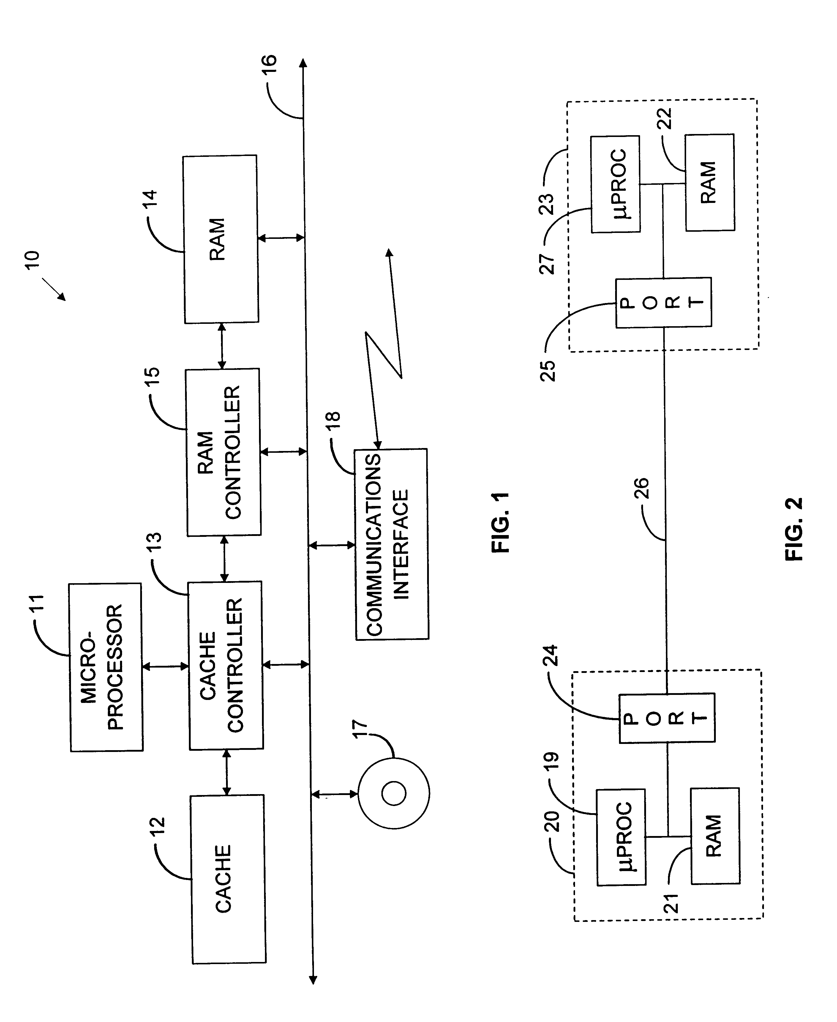
The demand-based coalescing to which the present invention is directed can be implemented in essentially all types of computer systems, but FIG. 1 depicts one type of computer system for the sake of concreteness. It is a uniprocessor system 10 that employs a single microprocessor 11. In FIG. 1's exemplary system, microprocessor 11 receives data and instructions for operating on them from on-board cache memory or further cache memory 12, possibly through the mediation of a cache controller 13. The cache controller 13 can in turn receive such data from system read / write memory (“RAM”) 14 through a RAM controller 15 or from various peripheral devices through a system bus 16.

The RAM 14's data and instruction contents, which can configure the system to implement the teachings to be described below, will ordinarily have been loaded from peripheral devices such as a system disk 17. Other sources include communications interface 18, which can receive instructions and data from other compute...


PUM


Abstract

A computer system (10) implements a memory allocator that employs a data structure (FIG. 3) to maintain an inventory of dynamically allocated memory available to receive new data. It receives from one or more programs requests that it allocate memory from a dynamically allocable memory “heap.” It responds to such requests by performing the requested allocation and removing the thus-allocated memory block from the inventory. Conversely, it adds to the inventory memory blocks that the supported program or programs request be freed. In the process, it monitors the frequencies with which memory blocks of different sizes are allocated, and it projects from those frequencies future demand for different-sized memory blocks. When it needs to coalesce multiple smaller blocks to fulfil an actual or expected request for a larger block, it bases its selection of which constituent blocks to coalesce on whether enough free blocks of a constituent block's size exist to meet the projected demand for them.

Description

BACKGROUND OF THE INVENTION1. Field of the InventionThe present invention concerns computer-memory allocators and in particular mechanisms that they employ for coalescing memory blocks.2. Background InformationSome of the instructions that a processor reads from its memory direct it to read data stored in other memory locations. The program as loaded often specifies the locations in which the data are to be stored: memory is allocated statically. But many programs generate large quantities of intermediate results that require only temporary storage. To use memory efficiently, memory should not be allocated to such results unless and until they are actually produced: it should be allocated dynamically. And, once the program no longer needs the data for which space was thus allocated, the program should be allowed to reuse that memory space.For this reason, most large programs employ a “heap” of dynamically allocable memory. As the program proceeds, various previously free memory bloc...

Claims


Application Information

Patent Timeline
Patent Type & Authority Patents(United States)
IPC IPC(8): G06F12/02
CPCG06F12/023Y10S707/99956Y10S707/99953
Inventor KNIPPEL, ROSS C.HELLER, STEVEN K.DETLEFS, DAVID L.
Owner ORACLE INT CORP
Why Eureka
Try Eureka