
Systems for controlling a drying cycle in a drying apparatus

a drying apparatus and drying cycle technology, applied in the direction of non-surface active detergent solvents, drying machines with progressive movements, organic/inorganic per-compound compounding agents, etc., can solve the problem that the drying of items cleaned with lipophilic fluid cannot be done automatically with the use of only a humidity sensor, and the drying of items cleaned with lipophilic fluid cannot be done automatically

Inactive Publication Date: 2005-01-11
THE PROCTER & GAMBLE COMPANY
View PDF134 Cites 47 Cited by
  • Summary
  • Abstract
  • Description
  • Claims
  • Application Information

AI Technical Summary

Benefits of technology

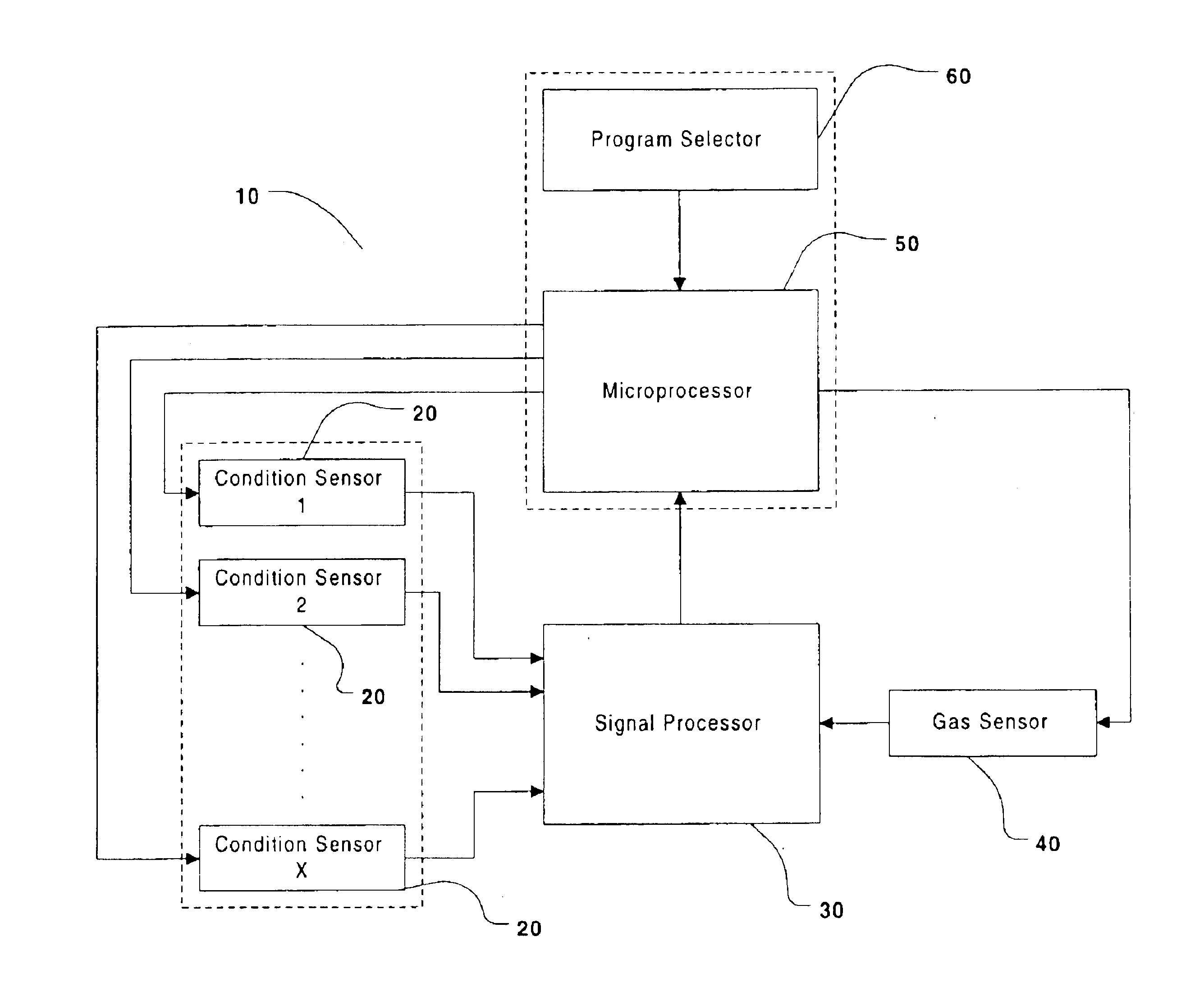
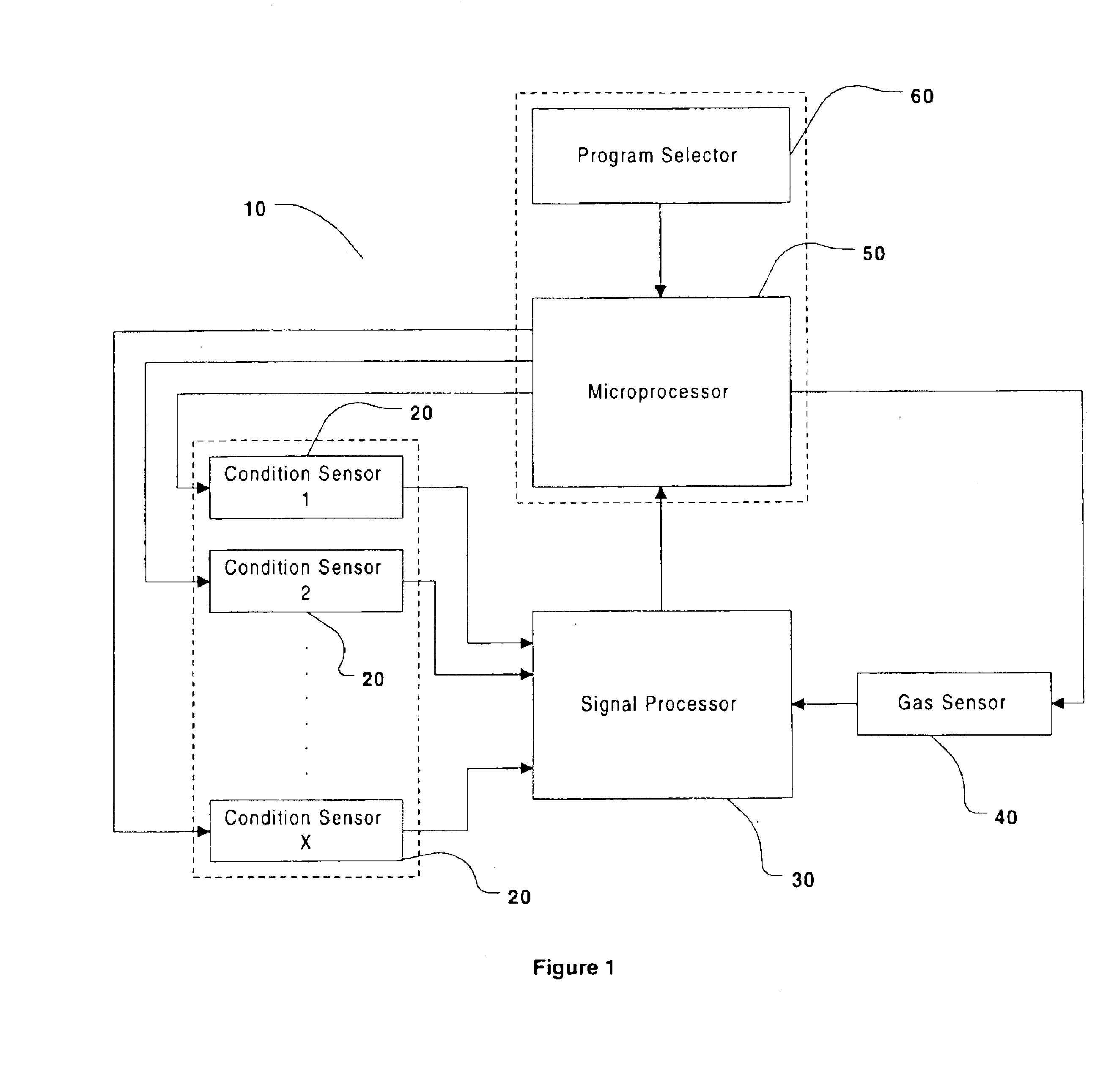
In a first embodiment, the present invention provides a system for controlling a drying cycle in a drying apparatus, wherein said drying apparatus comprises a lipophilic fluid vapor, a gas sensor capable of sensing the concentration of lipophilic fluid vapor present in said drying apparatus and transmitting a signal representative of the lipophilic fluid vapor concentration such that said drying cycle is controlled.
In a second embodiment, the present invention provides a system for controlling a drying cycle in a drying apparatus comprising, a condition detector and a gas sensor wherein said condition detector is capable of activating said gas sensor and said gas sensor is capable of generating a signal representative of the lipophilic fluid vapor concentration in the dryer such that the drying cycle is controlled.

Problems solved by technology

However, such conventional immersion cleaning techniques have proven unsatisfactory on a wide range of fabric articles that require special handling and / or cleaning methods due to fabric content, construction, etcetera, which may be unsuitable for immersion in water.
While the absence of water permits the cleaning of fabrics without the potential disastrous side effects water may cause, these lipophilic fluids do not perform well on hydrophilic and / or combination soils.
Along with this development, however, have arisen new problems.
Second, the drying of items cleaned with the lipophilic fluid cannot be done automatically with the use of only a humidity sensor.
Lastly, because these lipophilic fluids possess far greater fouling capabilities than water alone as well as potential flash point problems, sensors typically used in clothes dryers may not be suitable for use in lipophilic fluid clothes dryers.

Method used


Image

  • Systems for controlling a drying cycle in a drying apparatus
  • Systems for controlling a drying cycle in a drying apparatus
  • Systems for controlling a drying cycle in a drying apparatus

Examples


Embodiment Construction

Definitions

The term “lipophilic fluid” used herein is intended to encompass any non-aqueous fluid or vapor capable of removing sebum, as qualified by the test described below.

The term “fabrics” and “fabric” used herein is intended to mean any article that is customarily cleaned in a water-based laundry process or in a solvent-based dry cleaning process. As such the term encompasses bulk fabrics and fibers, as well as finished articles of clothing, linens, drapery, and clothing accessories. The term also encompasses other items made in whole or in part of fabric, such as tote bags, furniture covers, tarpaulins and the like.

The term “condition detector” used herein is intended to mean any detector and / or sensor capable of quantitatively and / or qualitatively measuring some scientific quality. These qualities may include, and are not limited to, time, temperature, fluid flow, and torque. Further, the measure may be of a physical quality within the drying apparatus (e.g., torque on the s...


PUM

PropertyMeasurementUnit
Fractionaaaaaaaaaa
Fractionaaaaaaaaaa
Timeaaaaaaaaaa

Abstract

The present invention relates to systems for controlling a drying cycle in a drying apparatus by monitoring the lipophilic fluid vapor concentration. The systems utilize a gas sensor capable of sensing the concentration of lipophilic fluid vapor in the drying apparatus drum or a combination of sensors / condition detectors, at least one of which is capable of sensing the concentration of lipophilic fluid vapor in the drying apparatus drum.

Description

FIELD OF THE INVENTIONThe present invention relates to systems for controlling a drying cycle in a drying apparatus by monitoring the lipophilic fluid vapor concentration. The systems utilize a gas sensor capable of sensing the concentration of lipophilic fluid vapor in the drying apparatus drum or a combination of sensors / condition detectors, at least one of which is capable of sensing the concentration of lipophilic fluid vapor in the drying apparatus drum.BACKGROUND OF THE INVENTIONConventional laundering techniques for the cleaning and treatment of fabric articles such as garments have long involved both traditional aqueous-based washing and a technique commonly referred to as “dry cleaning”. Traditional aqueous based washing techniques have involved immersion of the fabric articles in a solution of water and detergent or soap products, followed by rinsing and drying. However, such conventional immersion cleaning techniques have proven unsatisfactory on a wide range of fabric ar...

Claims


Application Information

Patent Timeline
IPC IPC(8): B01J20/28B01J20/22B01J20/26B01D15/00B01D17/02C11D3/30C11D11/00C11D3/37C11D3/39C11D3/16C11D3/26C11D3/43C11D3/20C11D3/40C11D7/02C11D3/395C10G33/00C10G33/02C11D7/50C11D3/50D06M23/00D06M23/06D06L1/00D06L1/10D06F58/28D06M13/00D06L3/00D06L1/12D06L3/02D06L1/02D06L1/04F26B21/14C11D7/22C11D7/26C11D7/24C11D7/32
CPCB01D15/00B01D17/0202F26B21/14B01J20/26B01J20/28014C10G33/02C11D3/162C11D3/2041C11D3/30C11D3/3765C11D3/3773C11D3/3905C11D3/3942C11D3/3945C11D3/3947C11D3/395C11D3/40C11D3/43C11D3/50C11D7/02C11D7/5004C11D7/5009C11D7/5013C11D7/5022C11D7/5027C11D11/0017C11D11/0076D06F58/28D06L1/02D06L1/04D06L1/10D06L1/12D06L3/026D06M13/005D06M23/06B01D17/04C11D3/3932C11D7/24C11D7/263C11D7/3209C11D7/3218D06F2058/2854D06L4/17D06F2103/00B29B2009/168B29B7/845D06F58/38D06F2103/28D06F25/00D06F2103/24D06F2103/32D06F2103/04D06F2103/38D06F2105/52C11D2111/48C11D2111/12
Inventor FRANCE, PAUL AMAAT RAYMOND GERARDRADOMYSELSKI, ARSENI VALEREVICH
Owner THE PROCTER & GAMBLE COMPANY
Learn More