Light guiding plate for backlight module

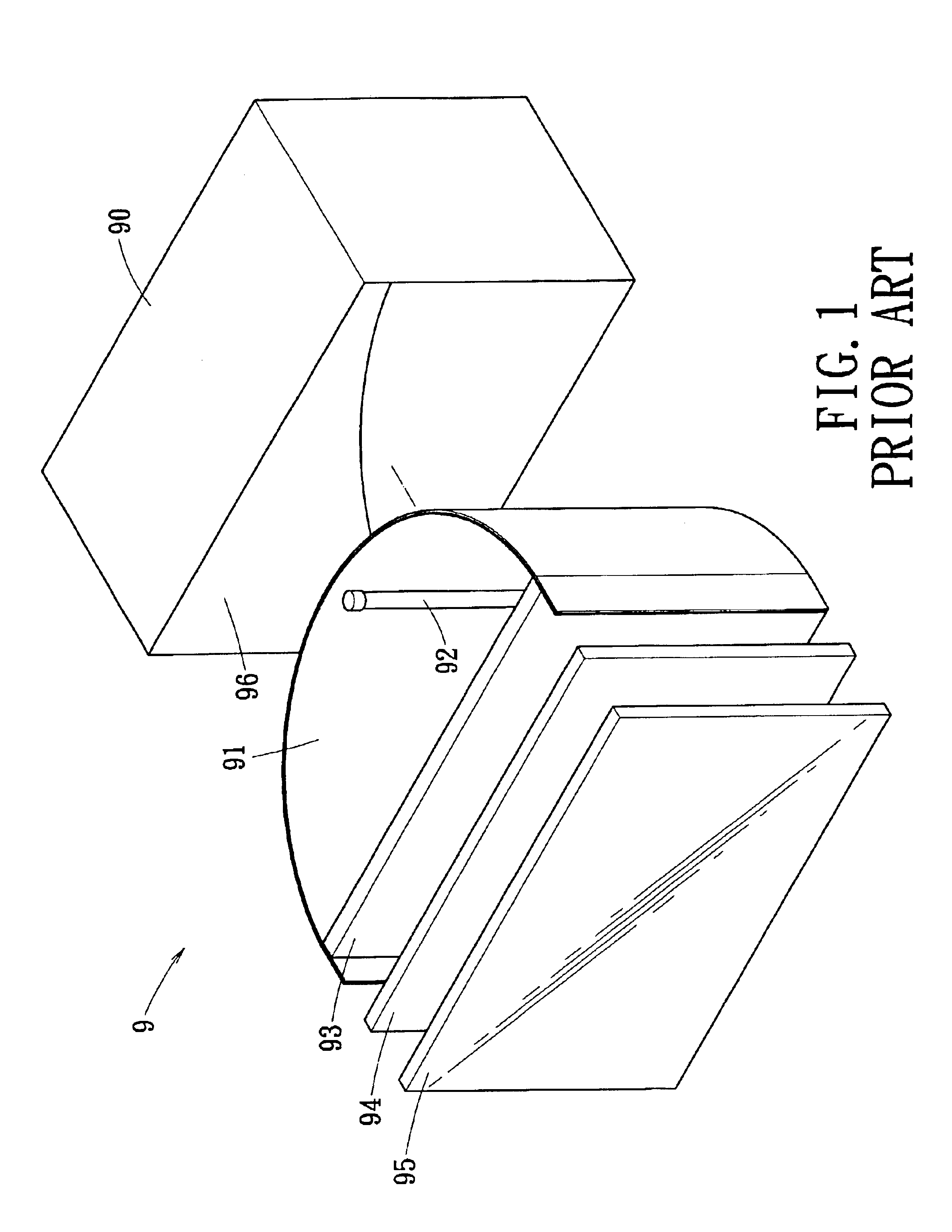
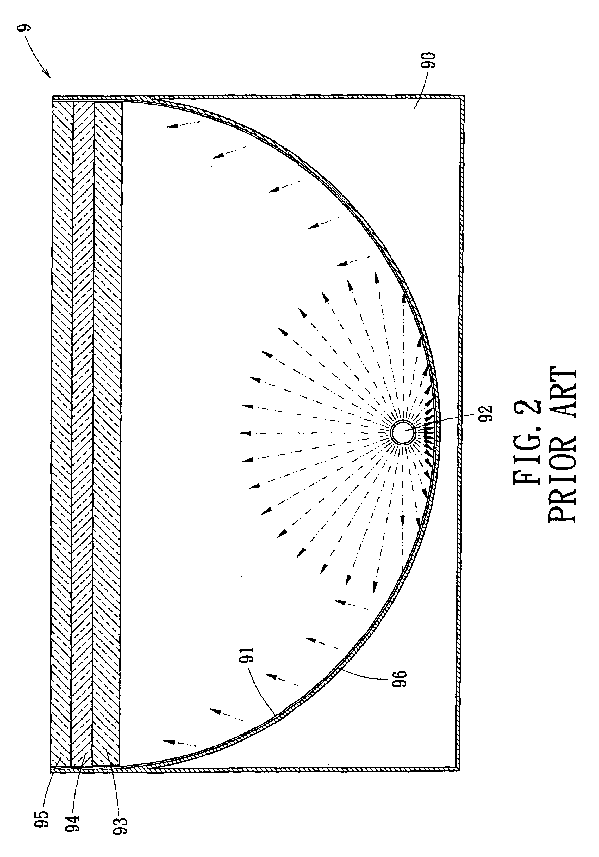
a technology of backlight module and light guide plate, which is applied in the field of light guide plate, can solve the problems of occupying space for the display of the crt, adversely affecting the glow of the vertical backlight module b>9/b>, etc., and achieves the reduction of the total thickness of the vertical backlight module, reducing the volume of the backlight module, and increasing the glow

Inactive Publication Date: 2005-01-11
KUO HENG SHENG
View PDF6 Cites 35 Cited by
  • Summary
  • Abstract
  • Description
  • Claims
  • Application Information

AI Technical Summary

Benefits of technology

It is another object of the invention to provide a light guiding plate by which the total thickness of the vertical backlight module is reduced to minimize the volume of the backlight module.
To accomplish the above and other objectives, the invention provides a light guiding plate that is mounted in a vertical backlight module between an illumination element and a diffusion plate. The light guiding plate has a flat light incidence surface at a bottom of the light guiding plate and a light emergence surface at a top of the light guiding plate. The light incidence surface faces the illumination element. The light emergence surface is adjacent to the diffusion plate and has a concave portion right above the illumination element. The concave portion of the light guiding plate further diffuses the light transmitted right above the illumination element to homogenize the light emergence and increase the glow for display of the backlight module. The total thickness of the vertical backlight module can be thus reduced to minimize the volume of the backlight module.

Problems solved by technology

A principal disadvantage of the CRT display therefore is the space occupied thereby.
As a result, the glow of the vertical backlight module 9 is adversely affected.

Method used


Image

  • Light guiding plate for backlight module
  • Light guiding plate for backlight module
  • Light guiding plate for backlight module

Examples


Embodiment Construction

Wherever possible in the following description, like reference numerals will refer to like elements and parts unless otherwise. illustrated.

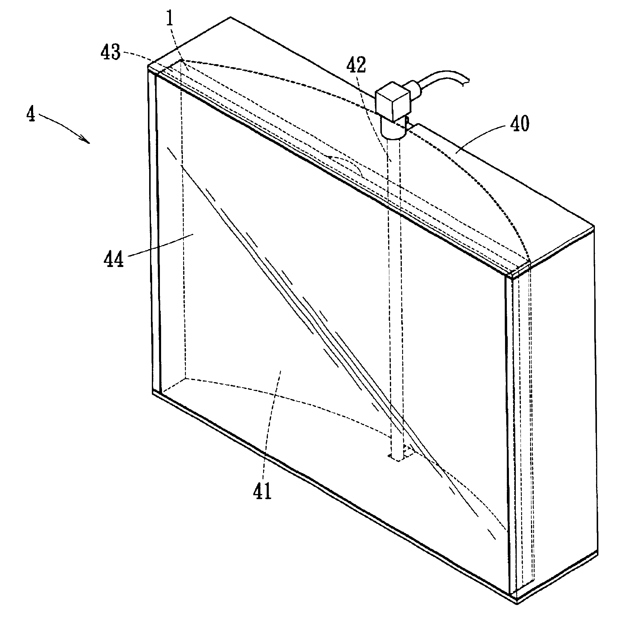
Referring to FIG. 3, the invention provides. a light guiding plate 1 that is flat and made of transparent material. At a bottom of the light guiding plate 1 is formed a flat light incidence surface 2. At a top of the light guiding plate 1 is formed a light emergence surface 3 with a concave portion 30. The concave portion 30 consists of segments with various curvatures being smoothly connected to one another.

Referring to FIG. 3 through FIG. 6, the light guiding plate 1 is mounted inside a vertical backlight module 4. The vertical backlight module 4 includes a base 40, a reflector 41, an illumination element 42, a diffusion plate 43, and a liquid crystal module 44. The base 40 is a rectangular solid and has a curved inner surface 45 to attach to the reflector 41. The illumination element 42 is mounted approximately in a central location of the ba...


PUM


Abstract

A light guiding plate according to the invention is mounted in a vertical backlight module between an illumination element and a diffusion plate. The light guiding plate has a flat light incidence surface at a bottom of the light guiding plate and a light emergence surface at a top of the light guiding plate. The light incidence surface faces the illumination element. The light emergence surface is adjacent to the diffusion plate and has a concave portion right above the illumination element. The concave portion of the light guiding plate further diffuses the light transmitted right above the illumination element to homogenize the light emergence and increase the glow for display of the backlight module. The total thickness of the vertical backlight module thereby is reduced to minimize the volume of the backlight module.

Description

BACKGROUND OF THE INVENTION1. Field of the InventionThe invention relates to a light guiding plate. More particularly, the invention provides a light guiding plate used in a vertical backlight module of a liquid crystal display, a scanner or an advertisement panel.2. Description of the Related ArtDisplay devices play an important role in communicating information through images. A CRT-type display device uses an electron beam to display images on a curved or flat panel. A picture tube of the CRT-type display device occupies a substantially large space to provide the necessary electron beam. A principal disadvantage of the CRT display therefore is the space occupied thereby.Recently, a compact display device such as a liquid crystal flat display has been developed and put into production. It has become popular due to its low weight and space saving advantages. Laptop computers are consequently made increasingly thinner and more compact by employment of liquid crystal displays, to fac...

Claims


Application Information

Patent Timeline
Patent Type & Authority Patents(United States)
IPC IPC(8): F21V3/00F21V5/00F21V8/00G09F13/04
CPCF21V3/00F21V5/00G02F1/133606H04N1/0289H04N1/02815H04N1/0285H04N1/02855H04N1/0287H04N1/02885G09F13/0409G02B3/06G02B5/10
Inventor KUO, HENG SHENG
Owner KUO HENG SHENG
Why Eureka
Try Eureka