Machining apparatus and machining method

a technology of machining apparatus and machining method, which is applied in the direction of grinding drives, manufacturing tools, other domestic objects, etc., can solve the problems of mechanical restriction of the speed or working efficiency of the cutting blade, the cost of tools rising to raise the cost of the working operation, and the inability to move the end mill in the circumferential direction of the cylindrical surface. to achieve the effect of improving the durability of the tool, the working efficiency and the roughness of the work surfa

Inactive Publication Date: 2005-01-11
TOYOTA JIDOSHA KK
View PDF26 Cites 16 Cited by
  • Summary
  • Abstract
  • Description
  • Claims
  • Application Information

AI Technical Summary

Benefits of technology

A main object of the invention is to improve the durability of a tool, a working efficiency and a roug

Problems solved by technology

Since the cutting blade is exposed to the cutting load at all times and is seriously heated to a high temperature, on the contrary, the cutting speed or the working efficiency is restricted by the life of the cutting blade.
In other words, if the cutting conditions are set by considering the working efficiency preferentially, the tool is so seriously worn as to cause a problem that the cost of tools rises to raise the cost of the working operation.
On the contrary, the speed to move the end mill in the circumferential direction of the cylindrical s

Method used


Image

  • Machining apparatus and machining method
  • Machining apparatus and machining method
  • Machining apparatus and machining method

Examples


examples

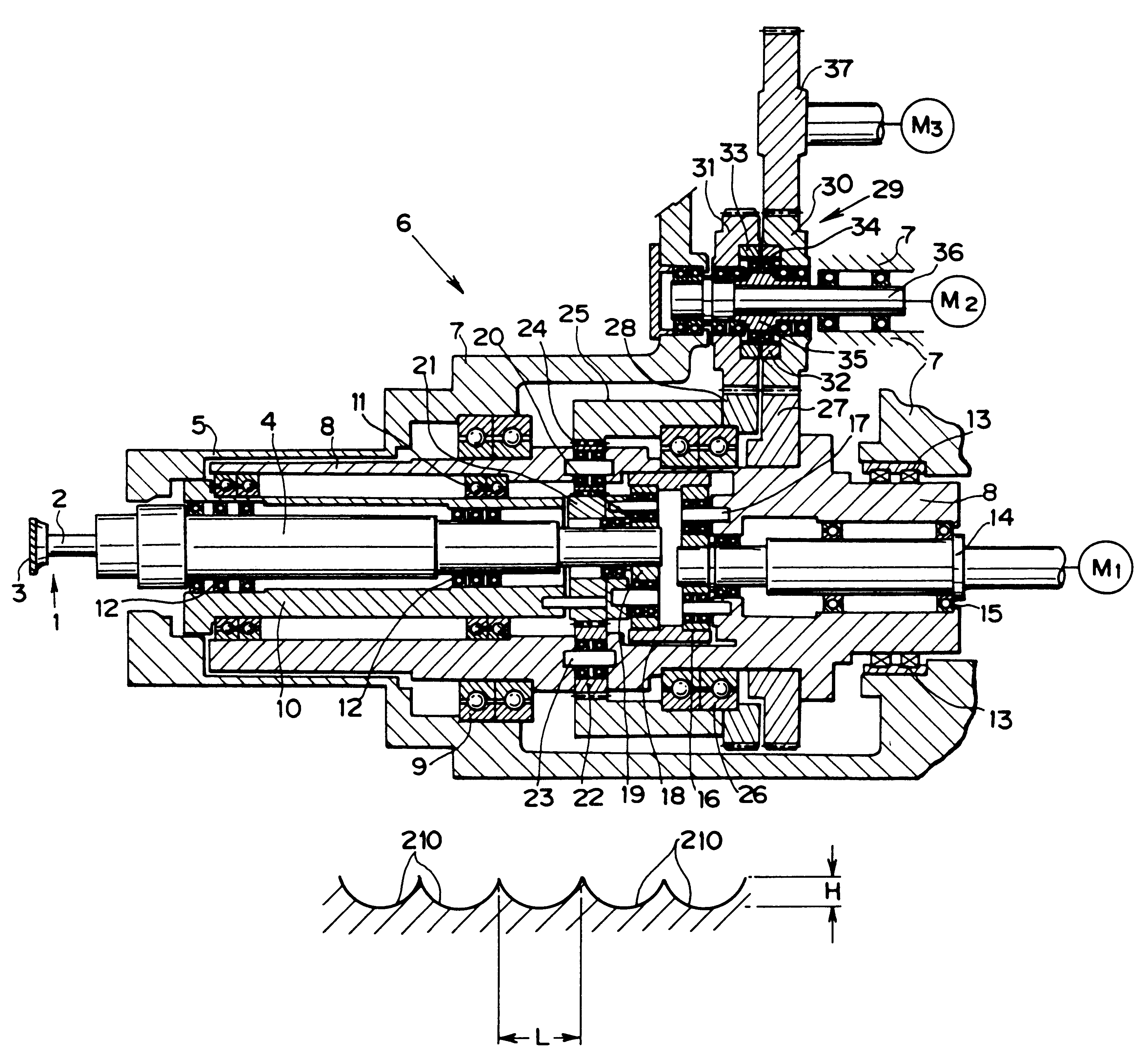
By employing a tool having a diameter DT of 60 mm and eight cutting blades (Z=8), a raw material bore having an internal diameter DW2 is worked to a worked bore having an internal diameter DW1. The tool is moved back and forth in the axial directions, while being rotated and revolved, to perform a rough working in the forward stroke and a finish machining in the backward stroke. The machining allowance in the radial direction is (DW1−DW2) / 2=1.5 mm, of which 1.3 mm is roughly cut out and 0.2 mm is cut out at the finish machining. On the other hand, the roughness H of the worked surface is 0.2 mm for the rough working and 0.005 mm for the finish machining. Moreover, the working efficiency Q is 50 cc / min. for the coarse working and 7.4 cc / min. for the finish machining. These values approximate those of the working efficiency for the boring operations. On the other hand, the cutting speed V is 250 m / min.

Under these conditions, the relations among the working efficiency Q, the rotation / r...


PUM

PropertyMeasurementUnit
Ratioaaaaaaaaaa
Surface roughnessaaaaaaaaaa

Abstract

A machining apparatus for machining a workpiece by rotating and revolving either the workpiece or a tool 1 to contact with each other. The machining apparatus comprises rotation/revolution ratio setting motors M1 and M3 for setting a ratio of a number of rotations to a number of revolutions of the workpiece or the tool 1, to a numerical value having a fraction below a decimal point, by changing the number of revolutions. The workpiece is machined by setting the number of revolutions and the number of rotations at the ratio.

Description

BACKGROUND OF THE INVENTION1. Field of the InventionThe present invention relates to a machining apparatus and a machining method for machining a workpiece by rotating a tool and the workpiece relatively and, more particularly, to an apparatus and a method for rotating and revolving either the tool or the workpiece.2. Related ArtA machining operation such as a cutting or grinding operation is generally performed by rotating a tool and a workpiece relative to each other. For example, a boring operation or cutting operation is performed by running the tool along a cylindrical surface of the workpiece to cut an inner face of the cylindrical surface continuously; similarly, an end milling operation for cutting an inner face of a cylindrical surface is performed by rotating a tool having cutting blades on its outer circumference to cut the inner face of the cylindrical surface and by moving the tool in the circumferential direction along the cylindrical surface so as to change portions t...

Claims


Application Information

Patent Timeline
IPC IPC(8): B23Q1/25B23Q1/54B23Q15/08B23C3/02
CPCB23Q1/5468Y10T29/49647Y10T82/12Y10T409/303808Y10T409/30056Y10T409/305656Y10T409/300784Y10T409/307616Y10T82/125Y10T82/10Y10T409/300112Y10T29/49668B23C2220/52
Inventor NONAKA, HIROKI
Owner TOYOTA JIDOSHA KK
Why Eureka
Try Eureka