Distributing device having continuously moving guide vanes

a technology of distributing device and guide rod, which is applied in the direction of mowers, agriculture tools and machines, mowers, etc., can solve the problems of guide rods and cannot solve, and achieve the effect of improving the distributing effect and relieving the load on the pivot bearings

Inactive Publication Date: 2005-01-11
DEERE & CO
View PDF21 Cites 75 Cited by
  • Summary
  • Abstract
  • Description
  • Claims
  • Application Information

AI Technical Summary

Benefits of technology

The rotating element can be provided with a hole that engages a pin, which is connected with the connecting rod. The pin is preferably arranged in an elongated hole in the element, so that a continuous adjustment of the amplitude of the pivoting movement can be performed by a variation in the position of the pin in the elongated hole. It would be conceivable to provide several holes in the element spaced at varying distances from the axis of rotation, into which the pin can be selectively inserted, instead of the elongated hole. Thereby a rotation of the pin in the holes about a connection, fixed against rotation, between the pin and the connecting rod is possible. On the other hand, in the case of an elongated hole the pin is fastened, as a rule, fixed against rotation, relative to the element, and the connecting rod rotates with respect to the drive.
Each guide vane can

Problems solved by technology

However, these known repositioning arrangements for the guide vanes

Method used


Image

  • Distributing device having continuously moving guide vanes
  • Distributing device having continuously moving guide vanes
  • Distributing device having continuously moving guide vanes

Examples


Embodiment Construction

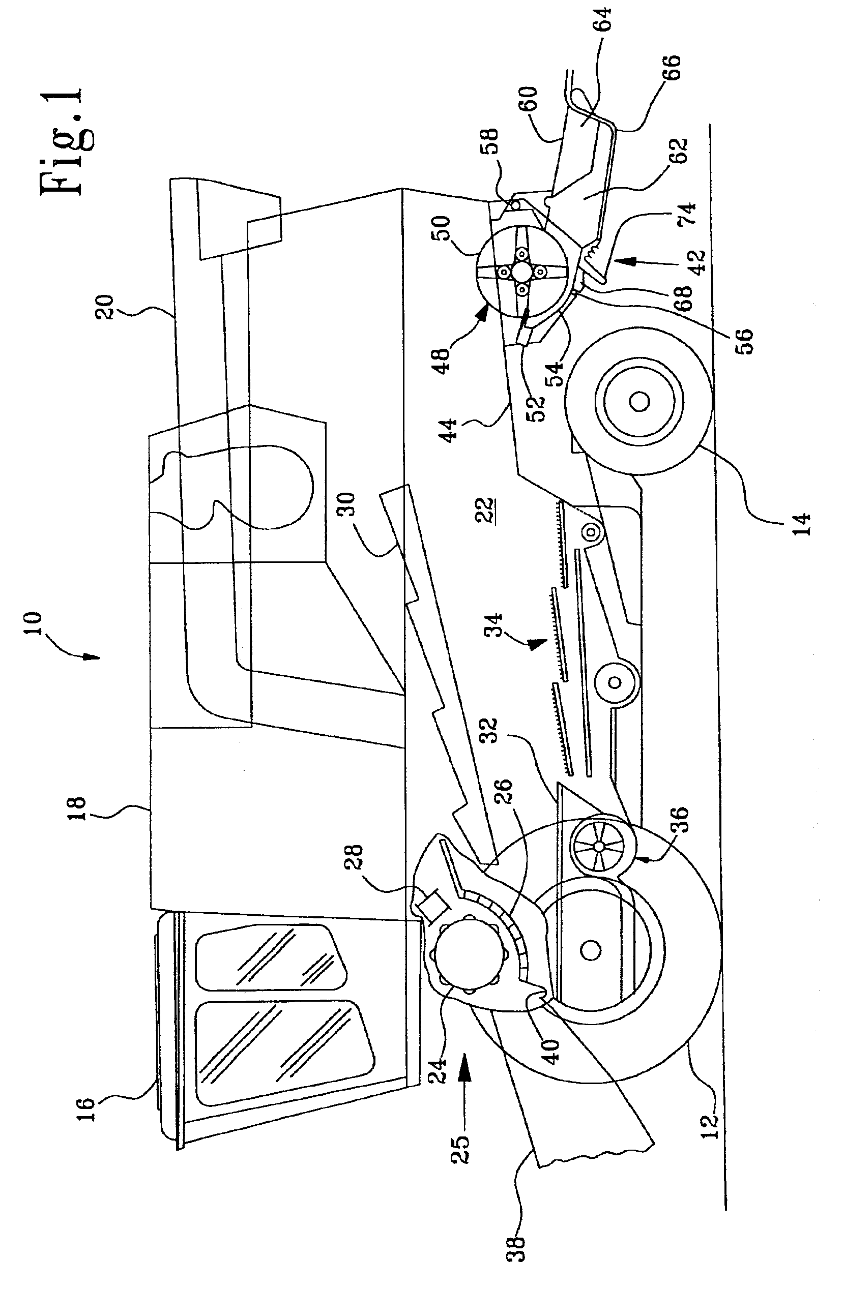
A harvesting machine 10, in the form of a combine, is carried on front driven wheels and rear steerable wheels 12 and 14. The combine is provided with an operator's cab 16 from which the combine is controlled. A grain tank 18 is located behind the operator's cab 16. The grain tank 18 is provided with a discharge auger 20. The grain tank 18 is supported on a frame 22 formed by the combine side sheets. A harvested crop is first cut by a harvesting platform, not shown, that directs the harvested crop to a feeder house 38. The feeder house 38 is an inclined conveyor and directs the harvested crop past a stone trap 40 to a threshing assembly 25 located between the side sheets. The threshing assembly 25 comprises a rotating threshing cylinder 24, a concave 26 and a rotating beater 28. The threshing assembly 25 separates the harvested crop into its large (straw) and small (grain and chaff) components. The large components and small components trapped therein pass over the concave 26 and ar...


PUM


Abstract

The invention is directed to a distributing device for a straw chopper arrangement. The chopper arrangement is provided with at least one guide vane for the transversely scattering the chopped straw. The position of the guide vane can be varied by a drive. In order to attain a uniform distribution of the chopped straw on the field the drive continuously moves the guide vane back and forth.

Description

FIELD OF THE INVENTIONThe present invention is directed to a distributing device for a chopper arrangement having at least one guide vane for the transverse scattering of the chopped straw, wherein the position of the guide vane, is varied back and forth by a drive.BACKGROUND OF THE INVENTIONDistributing devices with curved guide vanes are used to transversely deflect the remains of crop (straw) ejected by a chopper attached to the rear of a combine. The curvature of the guide vanes controls the transverse width of the distribution of the chopped straw so that it covers the transverse width of the cut crop. Under normal, dry conditions after leaving the guide vanes the chopped straw is braked by the air resistance and swirled about to a limited degree. As such, the straw is deposited on the ground in a uniform layer. With very moist crop or green crop and heavy straw, the air resistance cannot swirl the chopped straw as strongly. The straw leaves the guide vanes in the form of rays ...

Claims


Application Information

Patent Timeline
IPC IPC(8): A01F12/40
CPCA01F12/40
Inventor FOTH, CHRISTOPH
Owner DEERE & CO
Why Eureka
Try Eureka