Display device with a plurality of light-emitting tubes arranged in parallel

a technology of display device and light-emitting tube, which is applied in the direction of discharge tube luminescnet screen, identification means, instruments, etc., can solve the problems of difficulty in manufacturing light-emitting tube of the same shape and performance, and uneven luminance of light-emitting tube, so as to prevent irregular display of display device and variations of driving voltage

Inactive Publication Date: 2005-01-11
SHINODA PLASMA
View PDF6 Cites 47 Cited by
  • Summary
  • Abstract
  • Description
  • Claims
  • Application Information

AI Technical Summary

Benefits of technology

The present invention has been achieved in view of the above-mentioned problem. For manufacturing the display device with a plurality of light-emitting tubes arranged in parallel to each other as described above, an object of the present invention is to previously measure a p

Problems solved by technology

However, in such a display device, it is difficult to manufacture light-emitting tubes having the same shape and performance, and the luminance (light-emitting luminance) of the tubes is not uniform due to variations caused when the tubes are manufactured.
Thereby, when the light-emitting tubes are arranged in parallel to each other, non-uniformity of the luminance leads to irregular displ

Method used


Image

  • Display device with a plurality of light-emitting tubes arranged in parallel
  • Display device with a plurality of light-emitting tubes arranged in parallel
  • Display device with a plurality of light-emitting tubes arranged in parallel

Examples


embodiment 1

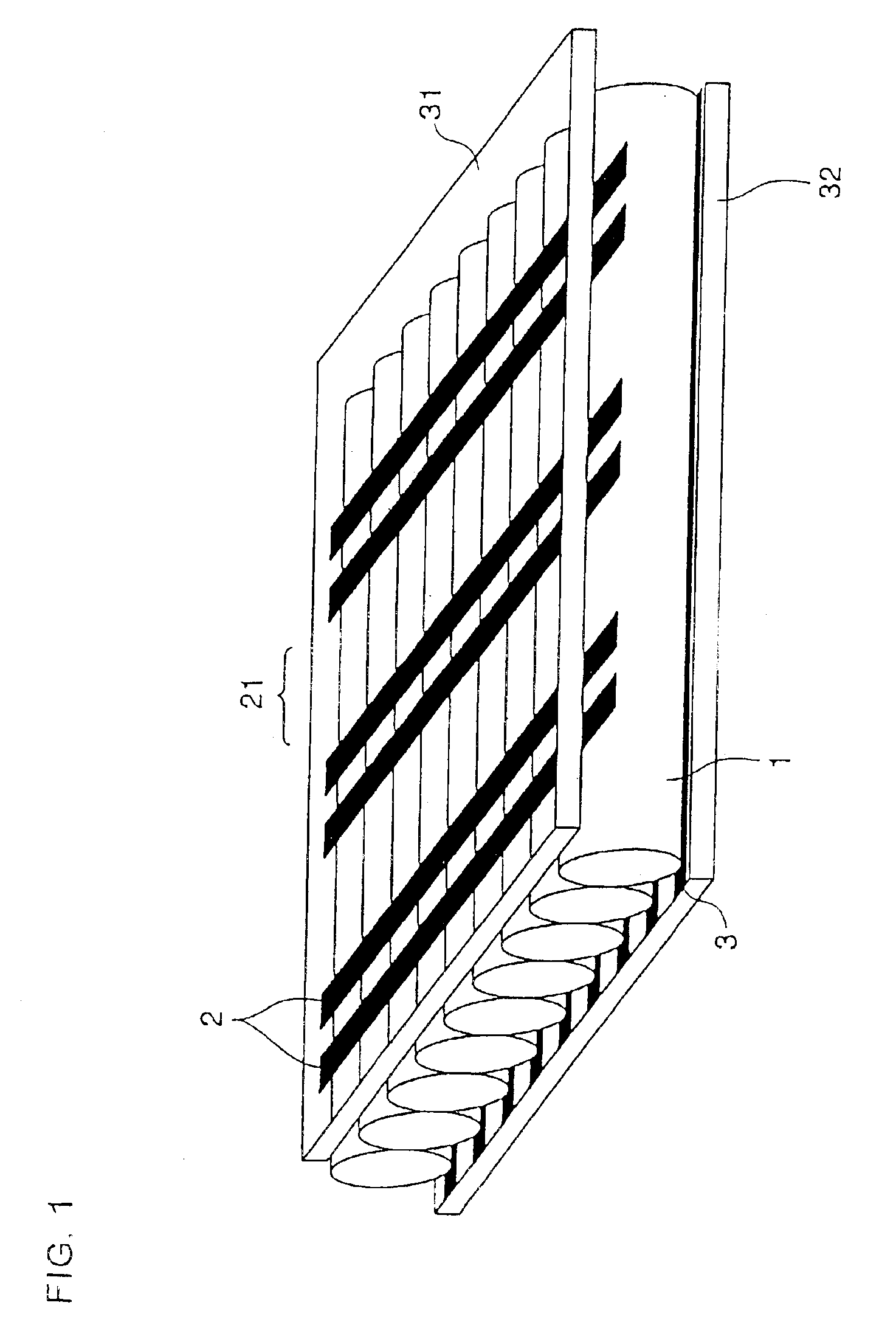
FIG. 2 is an exemplary view illustrating the construction of a display device of The figure shows a cross-sectional view of the display device.

In the present embodiment, a light-emitting tube, having a circular cross section, is formed of Pyrex® glass (a heat-resisting glass manufactured by Corning Inc. in U.S.A.) or the like to have an external diameter of 1 mm, a wall thickness of 100 μm and a length of 400 mm.

The tube 1 is obtained by manufacturing a base material similar to and larger than the tube 1 by Danner process and extending the base material while softening it by heating.

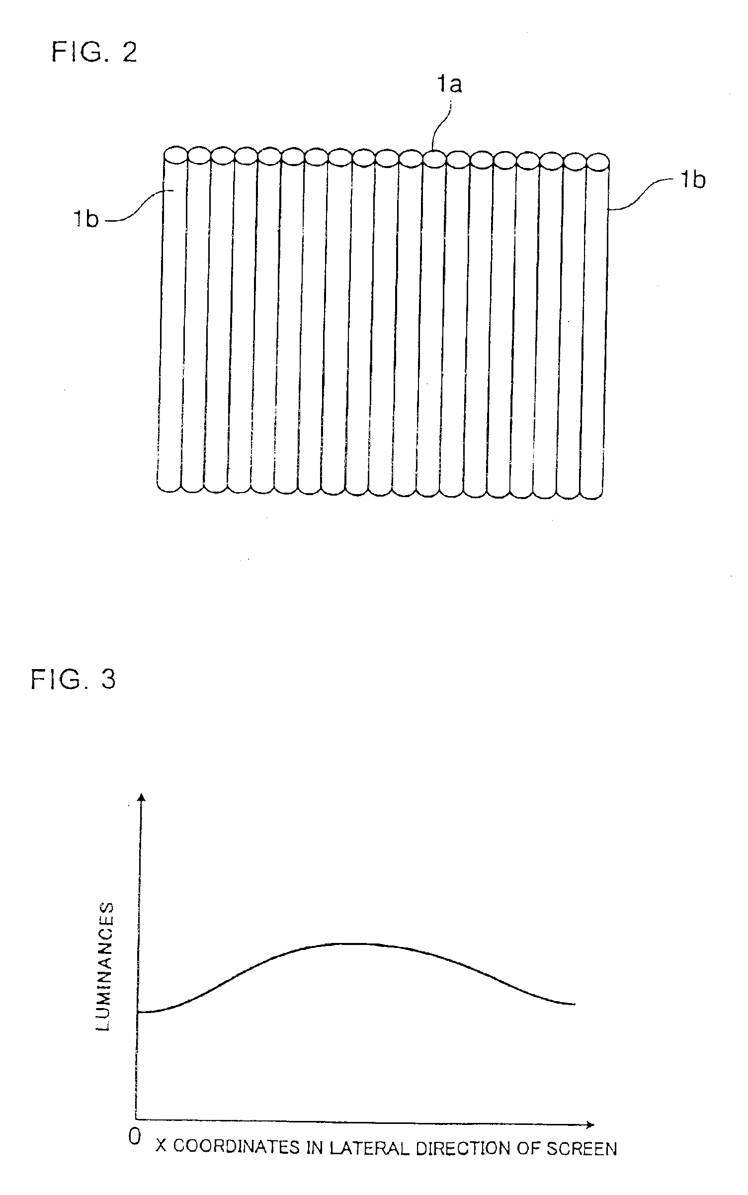
In the present embodiment, the plurality of light-emitting tubes are arranged in accordance with their luminance. In other words, a light-emitting tube 1a having a higher luminance is arranged at the center of the screen and tubes 1b having a lower luminance are arranged at left and right ends of the screen. The tubes have their own luminances determined in manufacture. Therefore, the luminances are pre...

embodiment 3

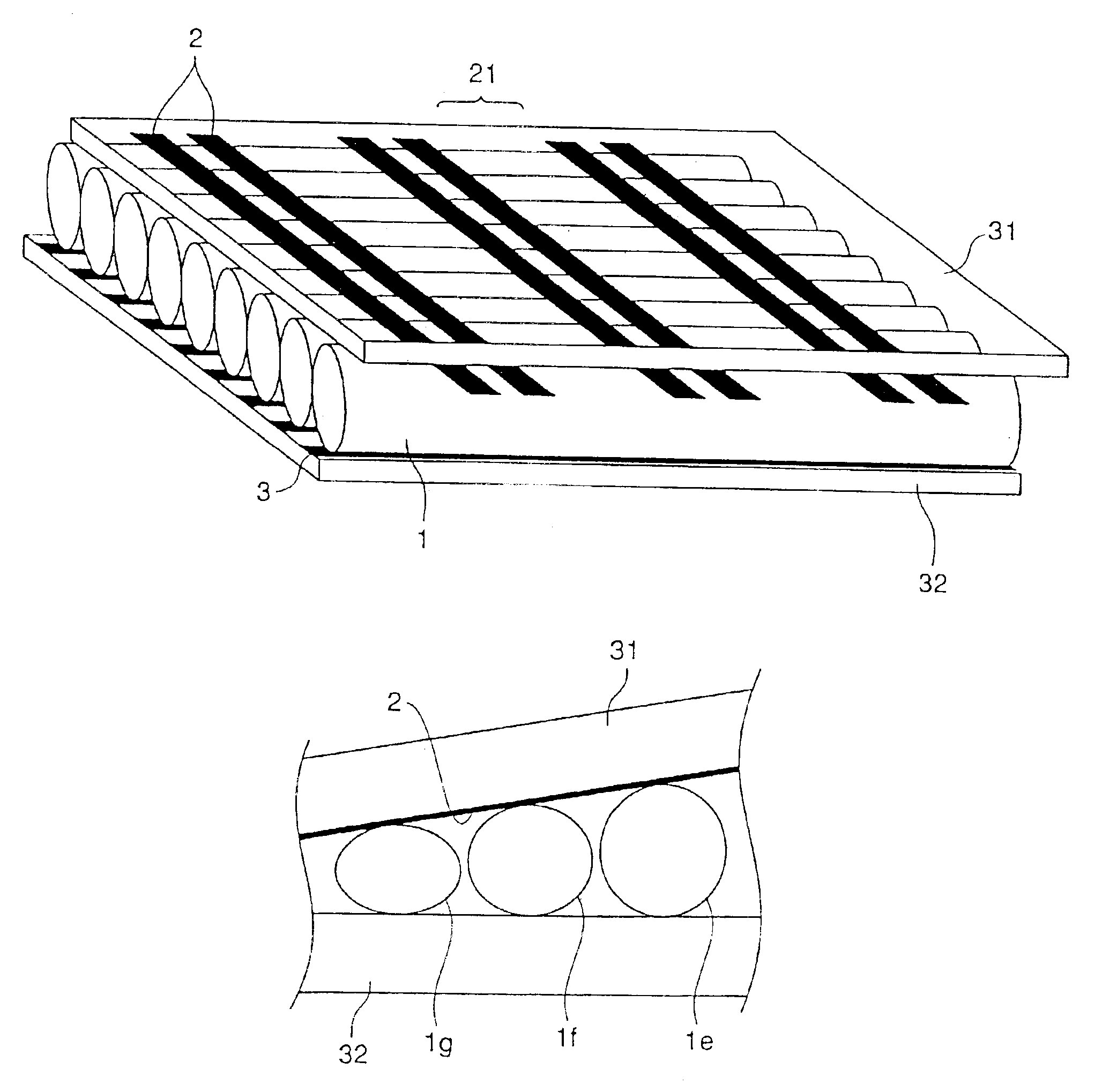
FIG. 9 is an exemplary view showing the construction of a display device according to This figure illustrates a section of the display device crossing at a right angle a longitudinal direction of the light-emitting tubes. In the present embodiment, the tubes are arranged in accordance with the dimension of external diameter.

In other words, a tube 1e having a large dimension of external diameter is arranged at one end (e.g., a right end) of the screen, a tube 1f having a middle dimension of external diameter is successively arranged at the center thereof and a tube 1g having a small dimension of external diameter is arranged at the other end (e.g., a left end) thereof. The tubes have their own dimensions of external diameter determined in manufacture. Therefore, the dimensions of external diameter are previously measured and then the tubes are arranged.

When the tubes are arranged in the order of dimension of external diameter as described above, contact areas between the display ele...

embodiment 4

FIG. 11 is an exemplary view illustrating the construction of a display device according to This figure shows a section of the display device crossing at a right angle a longitudinal direction of the light-emitting tubes. In the present embodiment, the tubes have an oblate spheroidal section and are arranged in accordance with the dimension of external diameter.

In the same manner as in Embodiment 3, a tube 1h having a large dimension of external diameter is arranged at one end (e.g., a right end) of the screen, a tube 1i having a middle dimension of external diameter is successively arranged at the center thereof and a tube 1j having a small dimension of external diameter is arranged at the other end (e.g., a left end) thereof. The tubes have their own dimensions of external diameter determined in manufacture. Therefore, the dimensions of external diameter are previously measured and then the tubes are arranged.

When the tubes are arranged in the order of dimension of external diame...


PUM


Abstract

A display device includes a plurality of light-emitting tubes arranged in parallel consisting of narrow tubes having a plurality of light-emitting points formed in a longitudinal direction thereof, a phosphor layer provided to the inside of each of the narrow tubes, and a discharge gas sealed into each of the narrow tubes. The plurality of light-emitting tubes are arranged in accordance with their property previously measured.

Description

CROSS-REFERENCE TO RELATED APPLICATIONThis application is related to Japanese Patent Application JP2002-138709 filed on May 14, 2002, whose priority is claimed under 35 USC § 119, the disclosure of which is incorporated by reference in its entirety.BACKGROUND OF THE INVENTION1. Field of the InventionThe present invention relates to a display device in which a plurality of light-emitting tubes (also referred to as “a plasma light-emitting tube”, “a display tube”, “a gas discharge tube”, “a plasma discharge tube” and the like) are arranged in parallel to each other. More particularly, it relates to a display device constructed by arranging a plurality of light-emitting tubes in parallel comprising narrow tubes of a diameter of about 0.5 to 5 mm each having a phosphor layer provided and a discharge gas sealed inside for displaying optional images.2. Description of the Related ArtA display device described in, for example, Japanese Unexamined Patent Publication No. 2000-315460 is well k...

Claims


Application Information

Patent Timeline
IPC IPC(8): G09F9/313H01J1/62H01J17/49H01J11/00H01J1/00H01J11/14H01J11/18H01J11/36
CPCH01J11/18A01K61/73E02B3/046E02B3/043
Inventor ISHIMOTO, MANABUSHINODA, TSUTAETOKAI, AKIRAYAMADA, HITOSHIAWAMOTO, KENJI
Owner SHINODA PLASMA
Why Eureka
Try Eureka