Marine electromagnetic measurement system

a technology of electromagnetic measurement and electromagnetic field, applied in the field of submarine exploration systems, can solve the problems of contamination of data and extremely sensitive magnetic sensors to nois

Inactive Publication Date: 2005-01-11
SCHLUMBERGER TECH CORP
View PDF23 Cites 169 Cited by
  • Summary
  • Abstract
  • Description
  • Claims
  • Application Information

AI Technical Summary

Problems solved by technology

These equivalent magnetic fields may therefore contaminate the data and must be removed from the data using digital signal processing techniques.
Moreover, the magnetic sensors are extremely sensitive to noise.

Method used


Image

  • Marine electromagnetic measurement system
  • Marine electromagnetic measurement system
  • Marine electromagnetic measurement system

Examples


Embodiment Construction

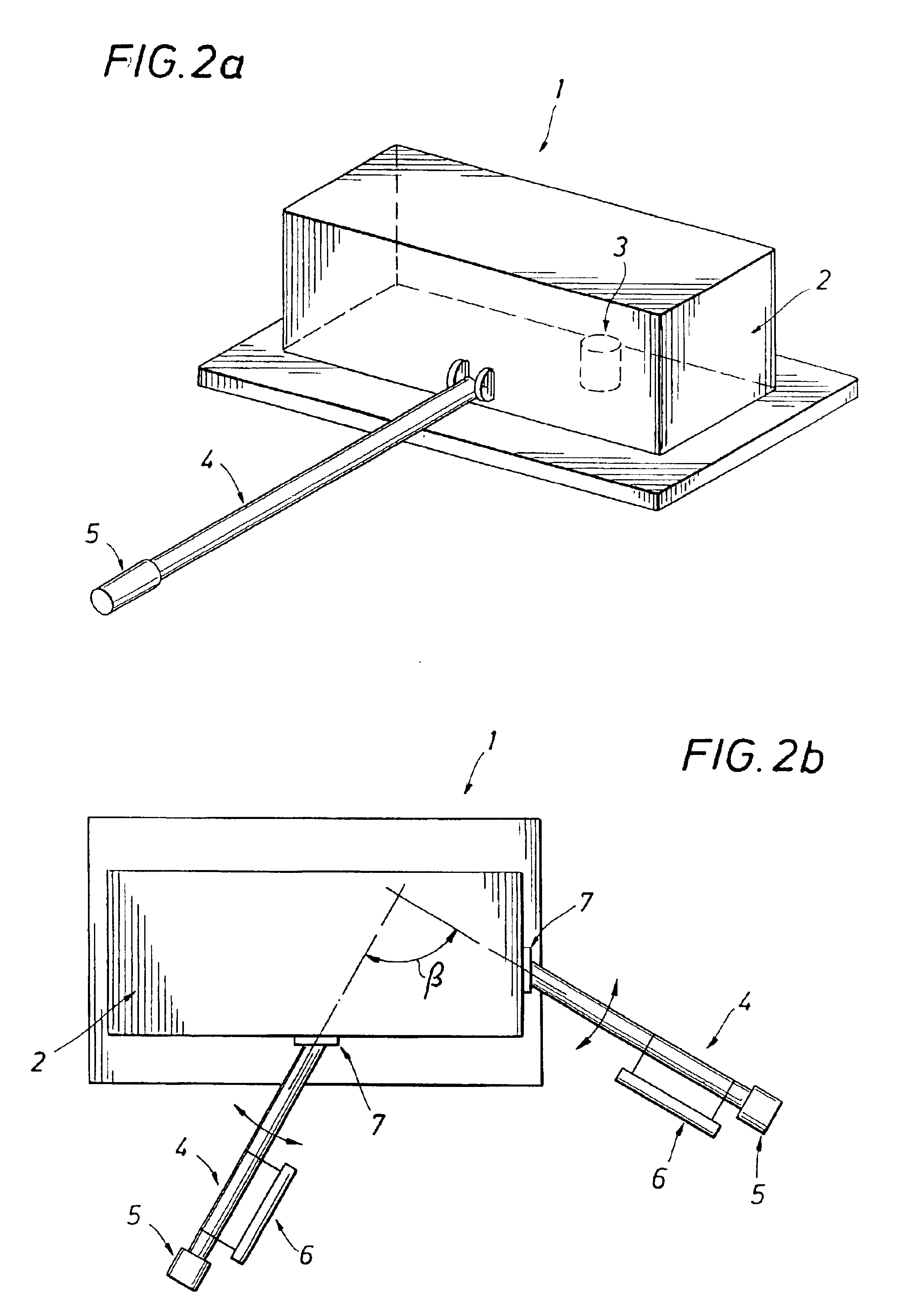
FIGS. 2a and 2b show subsea electromagnetic (EM) measurement systems according to the invention. FIG. 2a shows a subsea electromagnetic (EM) measurement system 1 that comprises a central structure 2 having an electrode 3 and attached to the central structure is at least one arm 4 pivotally coupled to the central structure 2. Electrode 3 can be at any location within the central structure 2. For example, electrode 3 can be attached to the central structure 2 and located within the interior end of arm 4, as shown in FIG. 6b. FIG. 2b shows a subsea electromagnetic (EM) measurement system 1 according to an embodiment of an invention, that comprises a central structure 2. A plurality of arms 4 is pivotally coupled to the central structure 2. An electrode 5 is coupled to each of the arms 4 proximate ends thereof, and at least two magnetometers 6 are coupled to the arms 4. The coupling 7 allows positioning the arms 4 and magnetometer 6 at substantially any angle (β) with respect to each ot...


PUM


Abstract

A sea-floor electromagnetic measurement device for obtaining underwater measurements of earth formations including a central structure and arms attached to the central structure so that they can pivot relative to the central structure. An electrode is attached to the end of each of the arms or to the central structure, and/or magnetometers are attached to the arms. A method for undertaking sea-floor electromagnetic measurements of earth formations including measuring electric fields at a selected distance from a central structure of an electromagnetic measurement system. Magnetic fields are then measured at the same location.

Description

BACKGROUND OF INVENTION1. Field of the InventionThe invention relates generally to subsea exploration systems. More specifically, the invention relates to a marine electromagnetic measurement system and a method of deploying and retrieving the same. One application for electromagnetic measurement systems is as a marine magnetotelluric receiver.2. Background ArtMagnetotelluric (MT) measurements are used to compute an electromagnetic impedance of selected earth formations. MT measurements are especially useful in regions where seismic imaging is inappropriate. For example, MT exploration is useful when evaluating geologic formations such as salts and carbonates. Salts, carbonates, and other particular formations may scatter seismic energy when seismic energy is propagated through them because of large velocity contrasts and inhomogeneties located within these formations, whereas the electromagnetic energy of the MT source fields propogates through these layers with less distortion. Th...

Claims


Application Information

Patent Timeline
Patent Type & Authority Patents(United States)
IPC IPC(8): G01V3/15
CPCG01V3/15
Inventor CONTI, UGONICHOLS, EDWARD
Owner SCHLUMBERGER TECH CORP
Why Eureka
Try Eureka