
Method for controlling delay time of signal in semiconductor device

a technology of delay time and semiconductor device, which is applied in the direction of pulse manipulation, pulse technique, instruments, etc., can solve the problem of inevitably determining the maximum delay time of input signals

Inactive Publication Date: 2005-01-11
SK HYNIX INC
View PDF4 Cites 20 Cited by
  • Summary
  • Abstract
  • Description
  • Claims
  • Application Information

AI Technical Summary

Benefits of technology

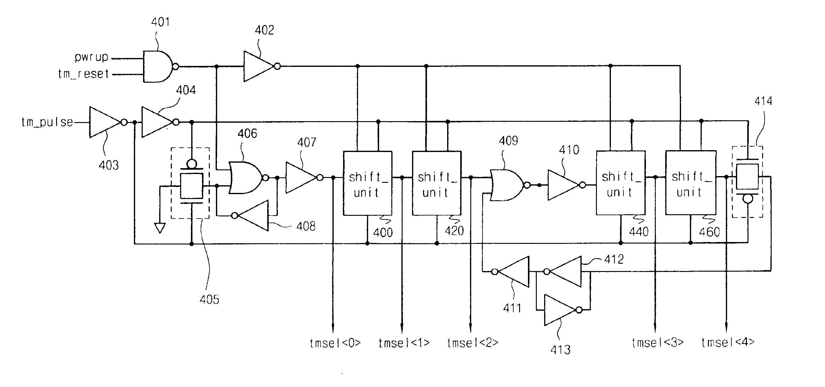
[0025]In the method, a falling point of the test mode pulse signal is adjusted, so as to adjust pulse widths of the Nth and the (N−1)th test mode selection signals, thereby adjusting the delayed time required for outputting the input signal as the output signal.

Problems solved by technology

That is, the prior art has a problem in that the maximum delay time of the input signal is inevitably determined depending on a total number of the delay devices.

Method used


Image

  • Method for controlling delay time of signal in semiconductor device
  • Method for controlling delay time of signal in semiconductor device
  • Method for controlling delay time of signal in semiconductor device

Examples


Embodiment Construction

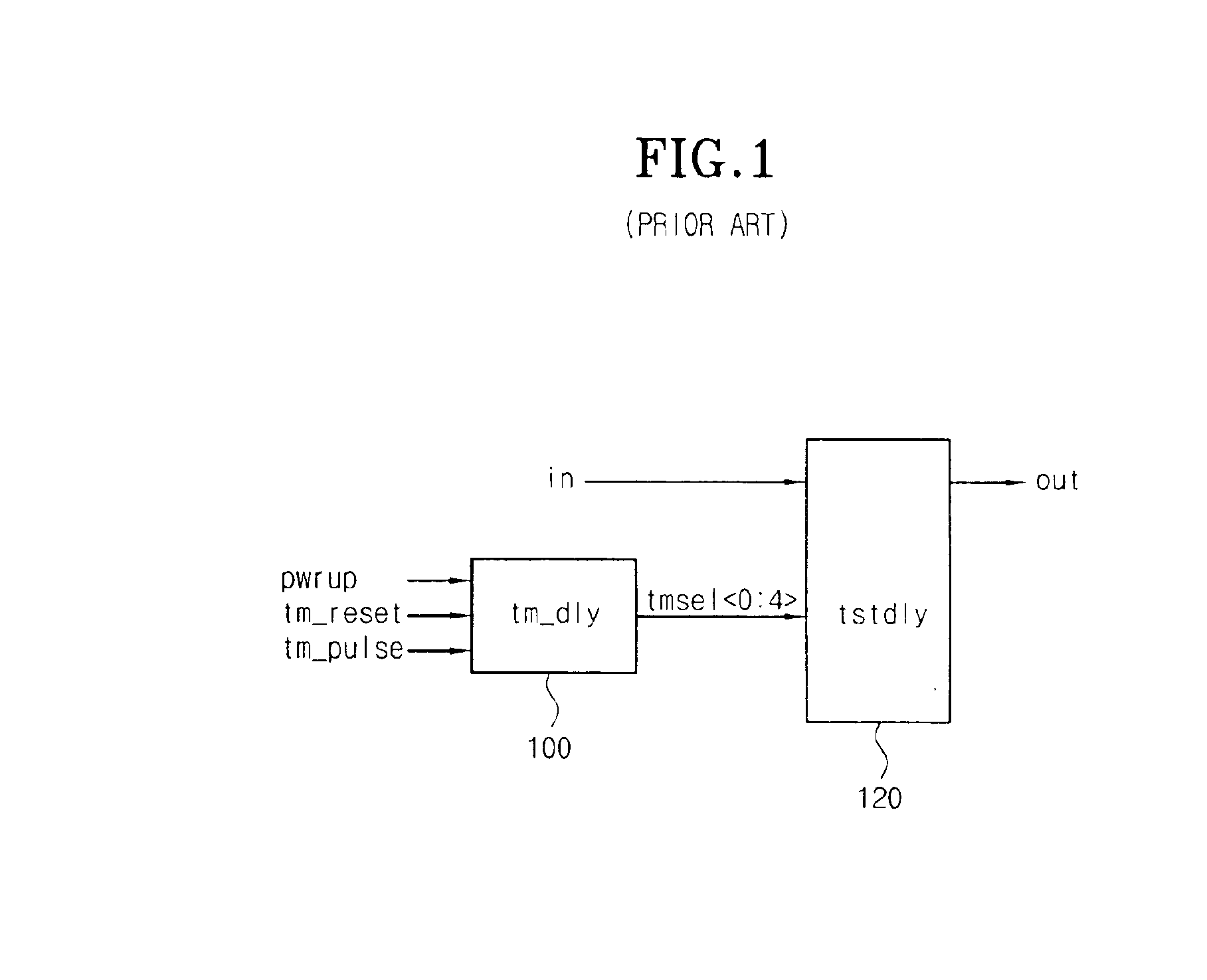
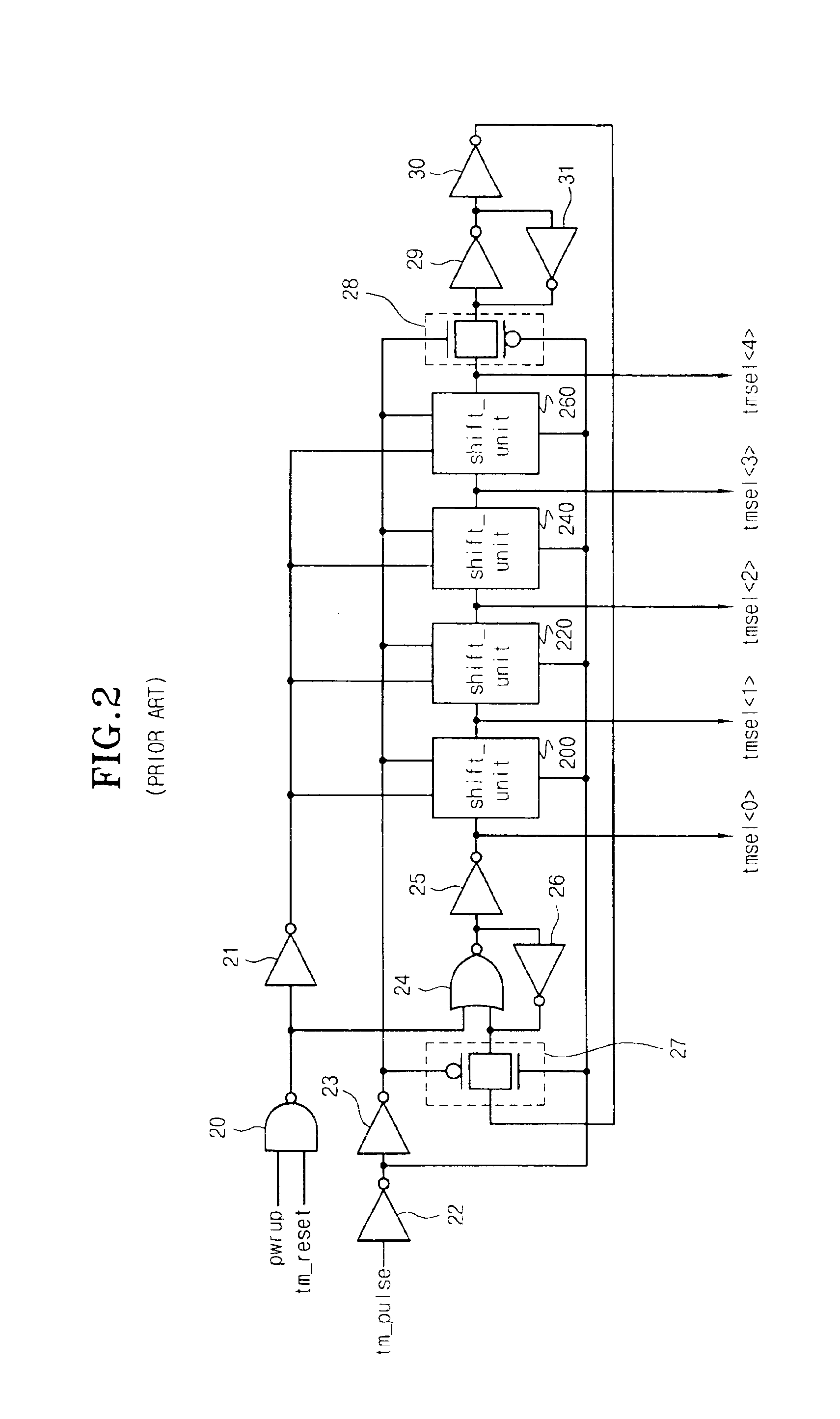
gram of a delay control circuit used in a semiconductor memory device;

[0036]FIG. 7 is a waveform view illustrating a simulation result of signals used in the delay control circuit utilized in a semiconductor memory device shown in FIG. 1;

[0037]FIG. 8 is a waveform view illustrating a simulation result of signals used in the test mode delay section shown in FIG. 4 according to the present invention;

[0038]FIG. 9 is a waveform view illustrating a simulation result of signals related to FIGS. 4 to 6: and

[0039]FIGS. 10a to 10c are waveform views according to the present invention.

DETAILED DESCRIPTION OF THE PREFERRED EMBODIMENTS

[0040]Hereinafter, a preferred embodiment of the present invention will be described with reference to the accompanying drawings.

[0041]FIG. 4 is a block diagram of a test mode delay section according to the present invention, and FIG. 5 is a block diagram of a test delay section according to the present invention. The test mode delay section generates a control si...


PUM


Abstract

A method for controlling a delay time of a signal in a semiconductor device is disclosed, which comprises the steps of: a) applying a test mode pulse signal; b) generating N number of test mode selection signals which are synchronized with the falling edges of the test mode pulse signal to respond sequentially; c) sequentially regenerating the (N−1)th test mode selection signal after the Nth test mode selection signal is generated; and d) repeating step c, wherein an input signal inputted to the semiconductor device is delayed by a predetermined time to be outputted as an output signal only when first to the (N−1)th test mode selection signals are enabled, and the delayed times are different from each other according to the first to the (N−1)th test mode selection signals. In the method, delay degree of a predetermined signal can be freely adjusted in a test mode. Further, a desired delay degree can be set by means of an external signal, regardless of the number of unit delay devices constituting a delay circuit.

Description

BACKGROUND OF THE INVENTION[0002]1. Field of the Invention[0003]The present invention relates to a method for controlling a delay time of a signal in a semiconductor device, which can freely adjust delay degree of a predetermined signal in a test mode, and more particularly to a method for controlling a delay time of a signal in a semiconductor device, which can set a desired delay degree by means of an external signal, regardless of the number of unit delay devices constituting a delay circuit.[0004]2. Description of the Prior Art[0005]In a general delay circuit, unit delay devices are connected in a row in order to make a desired delay time (i.e. delay degree). Further, in a test mode adjusting the delay degree, the number of unit delay devices, through which a signal inputted in the delay circuit passes, is adjusted by means of a predetermined control signal, so that the total delay degree (time) is adjusted. In this case, the variation of the delay is limited to an integral numb...

Claims


Application Information

Patent Timeline
IPC IPC(8): G01R31/28G01R31/26G11C8/00G01R31/30H03K5/13
CPCH03K5/131G01R31/3016G11C8/00
Inventor KIM, JI HYUNCHOI, BYOUNG JIN
Owner SK HYNIX INC
Learn More