
Inverse telecine conversion apparatus

a technology of telecine and conversion apparatus, which is applied in the direction of signal generators with optical-mechanical scanning, picture reproducers using projection devices, and television systems, etc., can solve the problems of deteriorating picture quality or the efficiency of compression of mpeg images

Inactive Publication Date: 2005-01-11
PIONEER CORP
View PDF6 Cites 22 Cited by
  • Summary
  • Abstract
  • Description
  • Claims
  • Application Information

AI Technical Summary

Benefits of technology

The present invention has been made to solve the problem above. Accordingly, an object of the present invention is to provide an inverse telecine conversion apparatus which accurately judges whether entered moving television picture information is originally television material or cinematic material and performs inverse telecine conversion based on a result of the judgement.

Problems solved by technology

Thus, there is a problem that the compression efficiency when compressing MPEG images or picture quality deteriorates due to the deletion of information which should be left undeleted.

Method used


Image

  • Inverse telecine conversion apparatus
  • Inverse telecine conversion apparatus
  • Inverse telecine conversion apparatus

Examples


Embodiment Construction

In the following, an embodiment of an inverse telecine conversion apparatus according to the present invention will be described with reference to the associated drawings.

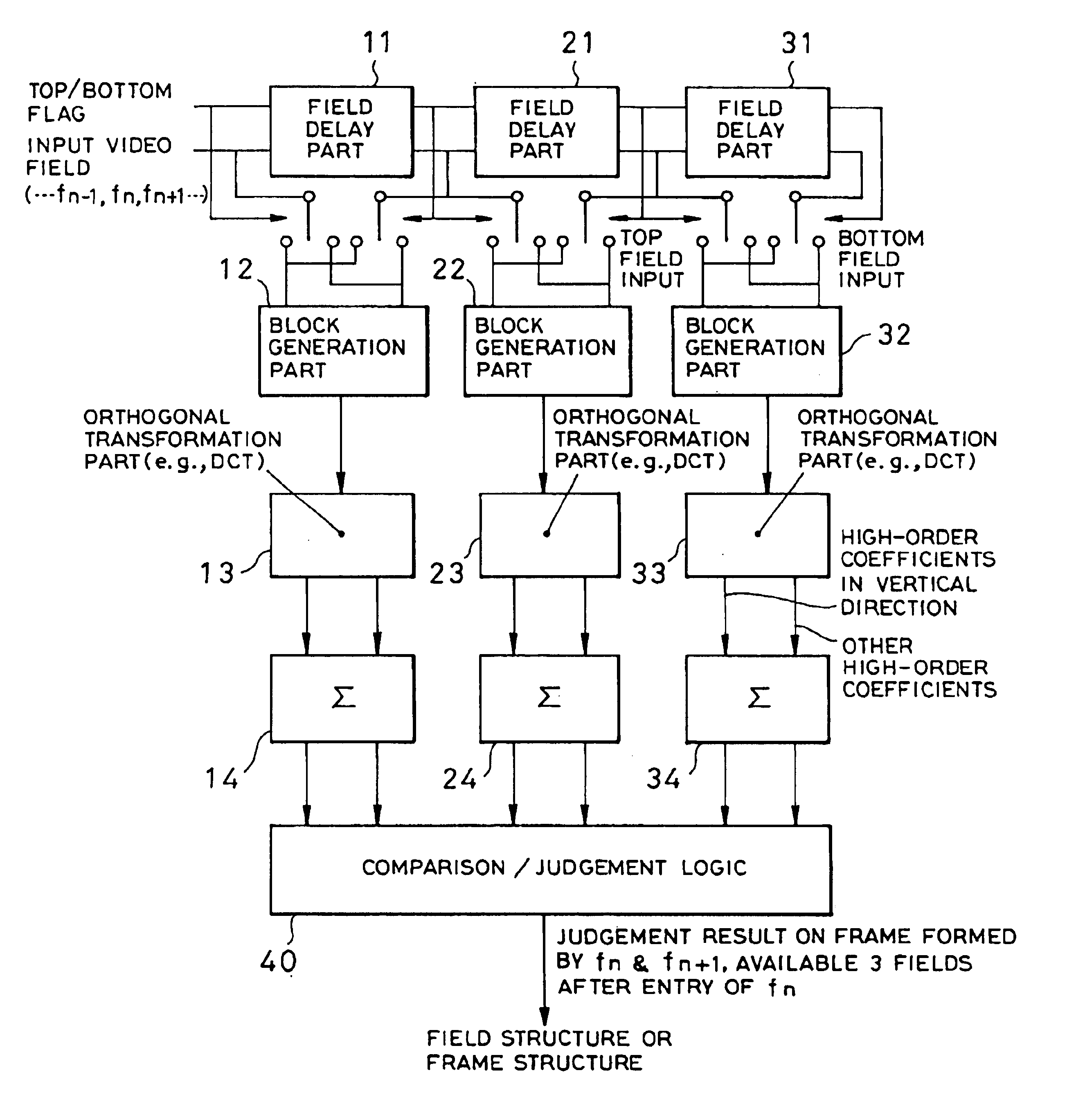
FIG. 4 is an overall structure diagram of the inverse telecine conversion apparatus. As shown in FIG. 4, the apparatus comprises a frame / field structure judging part 1, a delay part 2, and an inverse telecine conversion part 3.

First, the frame / field structure judging part 1 develops frame image information for judgement from adjacent pieces of field image information which are adjacent to each other in terms of time within entered moving television picture information, and judges a frame / field structure in the frame image information for judgement.

The inverse telecine conversion part 3, using a result of the judgement which the frame / field structure judging part 1 made regarding the frame / field structure, judges whether an input video signal supplied through the delay part 2 is a television material or a cinematic ...


PUM


Abstract

An inverse telecine conversion arrangement and methodology that accurately judges whether entered moving television picture information is originally a television material or a cinematic material, and performs inverse telecine conversion based on a result of the judgement. The apparatus includes a structure judging portion which judges whether a structure is a frame structure or a field structure based on adjacent pieces of field image information in the received moving television picture information which are adjacent to each other in terms of time; and a pattern judging portion which determines that the received moving television picture information has a predetermined pattern based on a pattern in which a field structure and a frame structure judged by the structure judging portion are successive to each other, and when the pattern judging portion recognizes the predetermined pattern, a corresponding piece of the received moving television picture information is inverse telecine converted.

Description

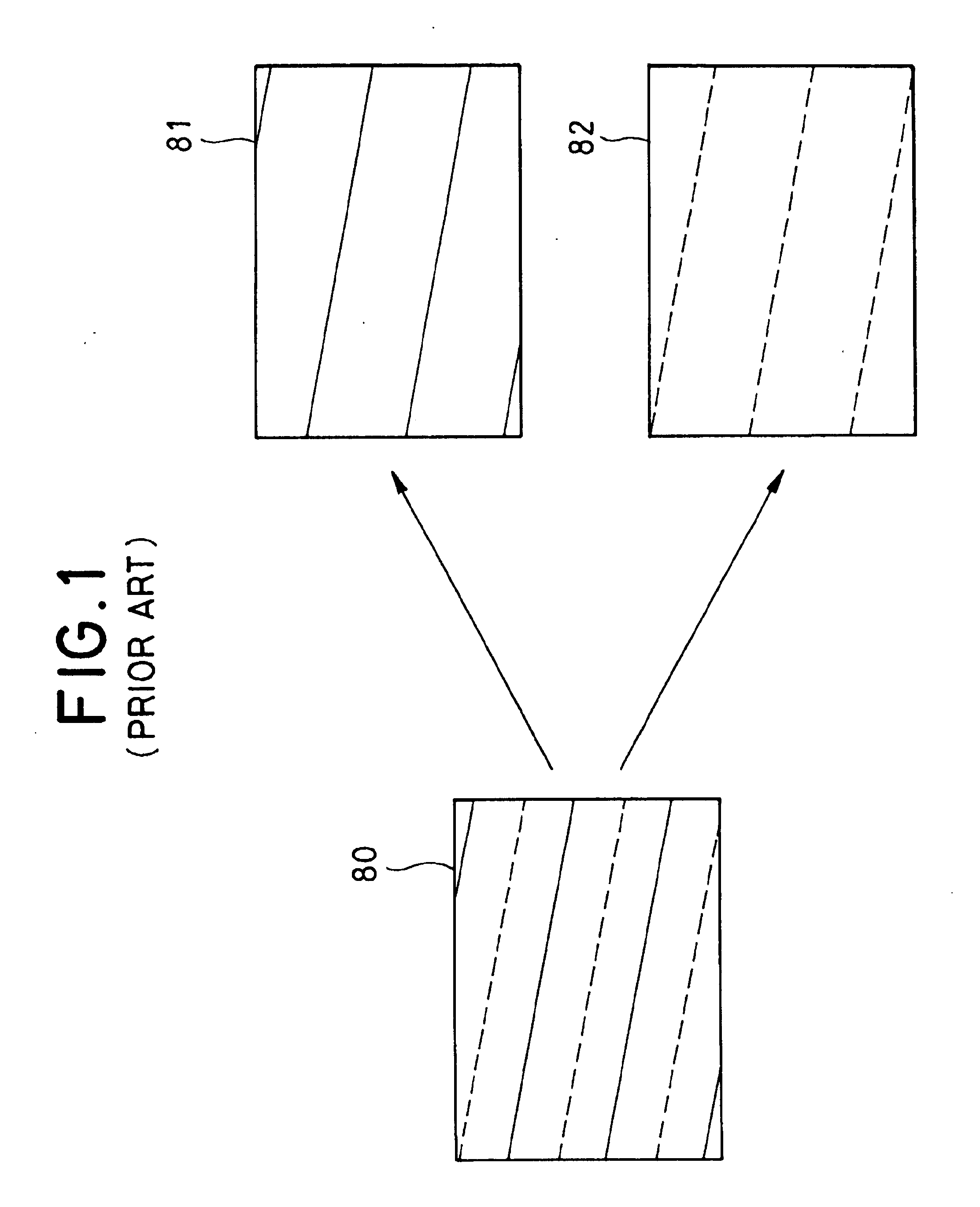
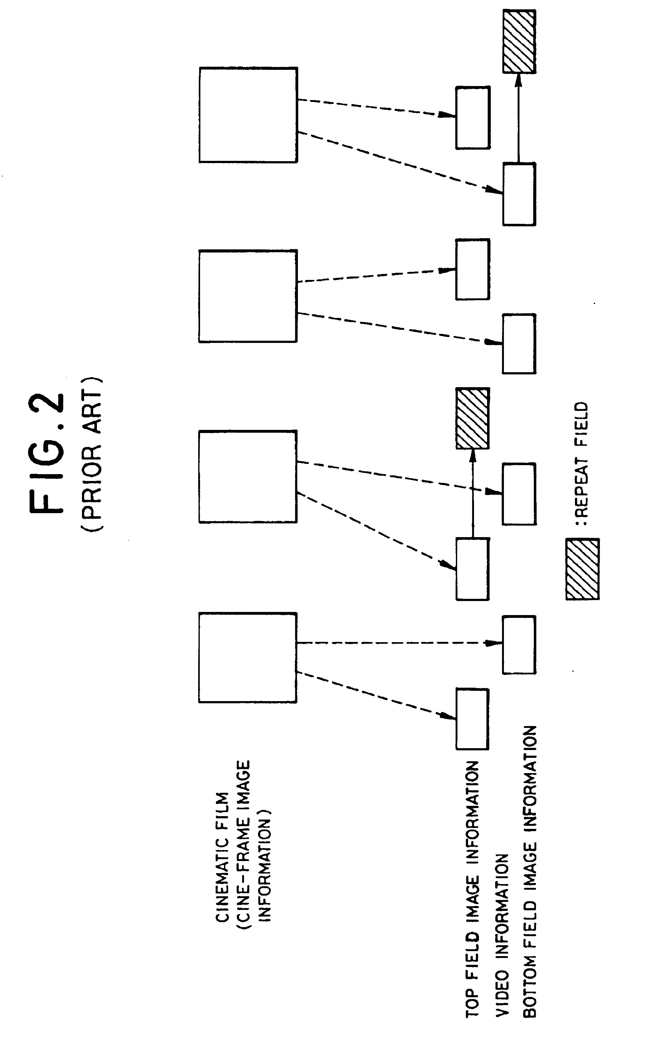
BACKGROUND OF THE INVENTION1. Field of the InventionThe present invention relates to an inverse telecine conversion apparatus, for use in a recording apparatus using an MPEG (Moving Picture Expert Group) encoding technique such as a DVD (Digital Versatile Disk) recorder, which converts moving television pictures simulated from cine-frame images into the original cine-frame images.2. Description of Related ArtMoving pictures of a cinematic film that are cinematic materials are displayed on a screen with 24 frames per second of display information shown continuously over time.On the other hand, moving television pictures which are television materials are displayed with 30 frames of image information (hereinafter “frame image information”) per second, continuously over time on a display. As shown in FIG. 1, top field image information 81 and bottom field image information 82 are combined with each other and scanned over, thereby defining frame image information 80.When television vide...

Claims


Application Information

Patent Timeline
IPC IPC(8): H04N7/01H04N5/253
CPCH04N7/0112
Inventor SUGIHARA, MOTOOKI
Owner PIONEER CORP
Learn More