Pressure-ball sliding doorstop

a technology of sliding doors and pressure balls, applied in the field of door stops, can solve the problems of complex construction and function, increase production costs, etc., and achieve the effect of efficient manufacturing, high stop force absorption, and precise construction

Inactive Publication Date: 2005-01-18
EDSCHA ENG GMBH
View PDF27 Cites 52 Cited by
  • Summary
  • Abstract
  • Description
  • Claims
  • Application Information

AI Technical Summary

Benefits of technology

The arrangement of a continuous longitudinal groove with a complementary profile to the cap through brake ramps and catch depressions forms a precise lateral guide for the brake and / or stop bodies over the entire length, without increasing the contact pressure per unit area.
The integral design of an abutment or limit stop on the door retaining rod corresponding to the open position of the door advantageously permits a precise construction, in which additional toleranced components can be dispensed with. Swiveling the door and the resulting longitudinal displacement of the door retaining rod in relation to the housing of the retainer piece lead to a swivel movement of the door retaining rod about its pivot axis. An embodiment, in which the walls of the opening arranged perpendicular to the guide openings have arches over the width of the opening, which guide the door retaining rod laterally and the convexly rounded dome heads of which are arranged on a level with the center axis of the guide openings and align with their inner wall, advantageously allows the door retaining rod to swivel out.
An embodiment in which the bearing eye is extended by forming the metal core parallel to the pivot axis advantageously allows very high stop forces to be absorbed. If the opening is dimensioned so that the door retaining rod can be introduced with its end having the bearing eye foremost, this advantageously means that the door retaining rod can have an integral abutment at the other end without this impeding assembly.
Designing the closing cap of the brake and / or stop body with approximately equal wall thicknesses advantageously allows the brake and / or stop bodies to be efficiently manufactured from plastic by the injection molding process whilst ensuring high strength and stability. Designing the outer surface of the cylindrical part of the brake and / or stop bodies with channels running in the direction of movement permits a favorable distribution of slide lubricants and reduction of the contact surface and hence the frictional resistance between brake and / or stop body and inner surface of the guide opening, without adversely affecting the precise and tilt-free guiding of the brake and / or stop bodies in the cylindrical guide opening.
The provision of underside fixing apertures in the metal frames for fixing the doorstop to a door assembly piece advantageously permits an alternative design with internal thread or with press-in screws affording a highly flexible variation of the hole piercing.
The integral arrangement of cushions of elastic material on the upper end surface of the housing reduces the overall dimensions and allows the doorstop to be designed using fewer parts.

Problems solved by technology

The construction and function moreover becomes complex and expensive.

Method used


Image

  • Pressure-ball sliding doorstop
  • Pressure-ball sliding doorstop
  • Pressure-ball sliding doorstop

Examples


Embodiment Construction

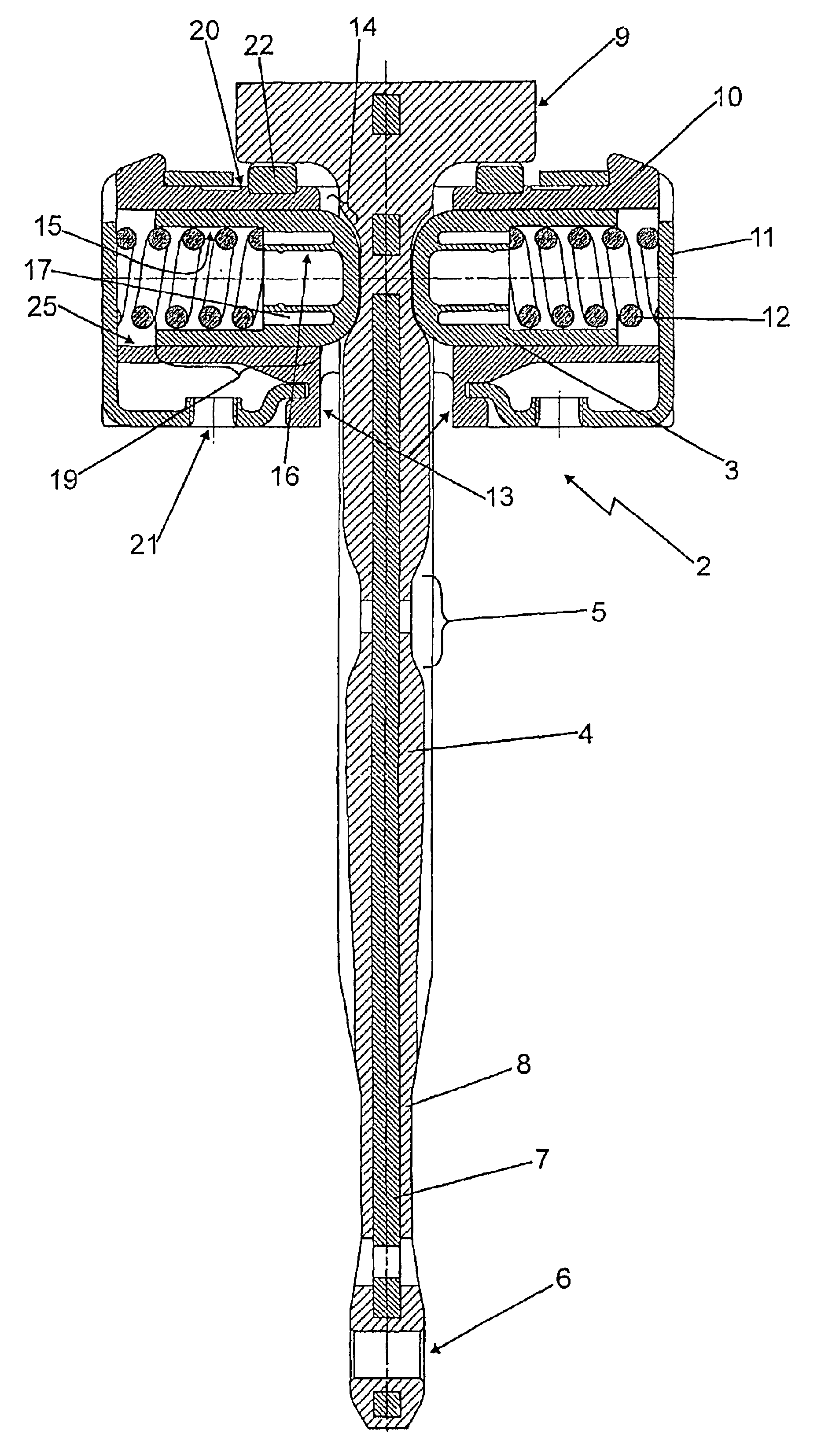
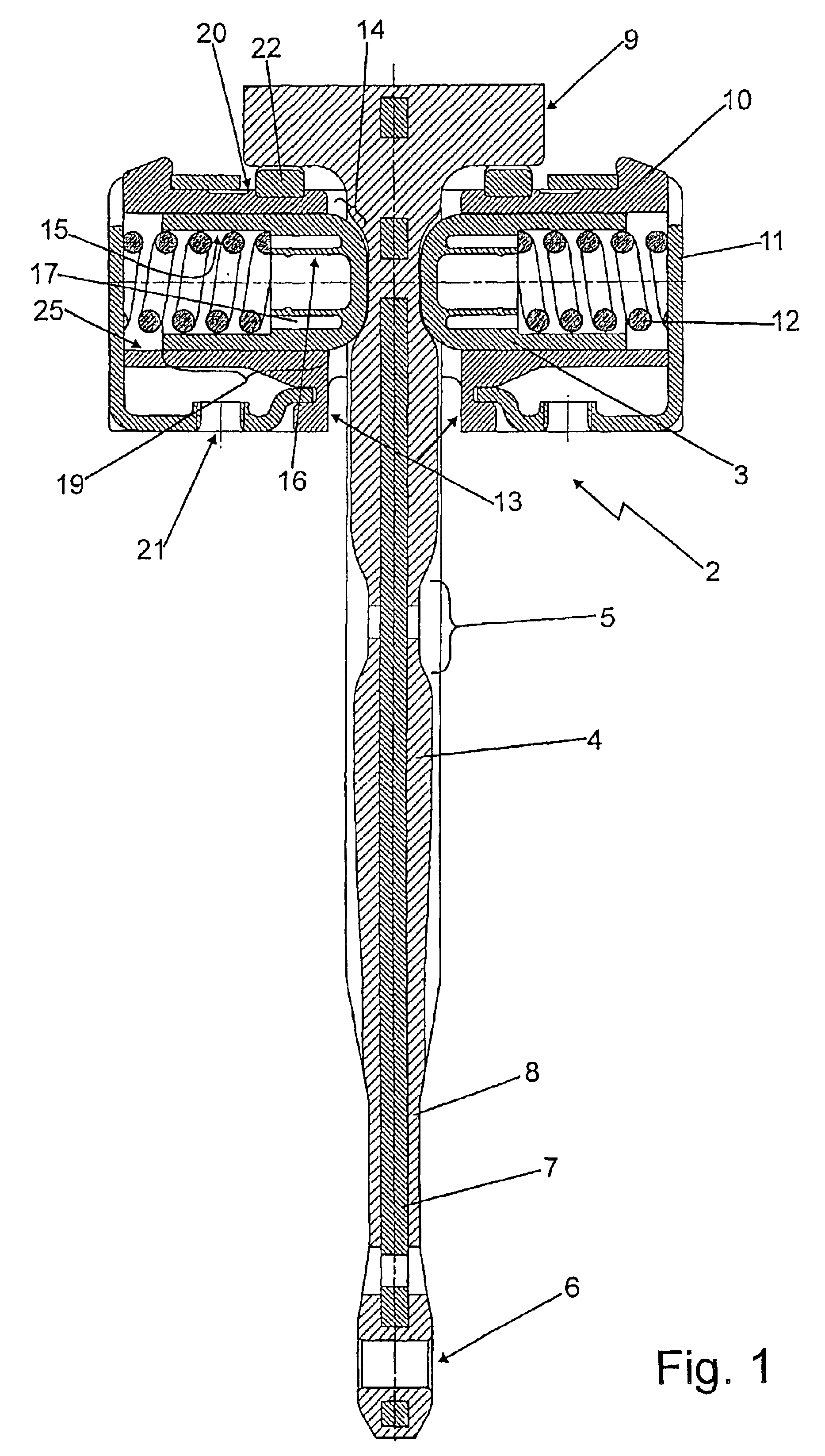
FIG. 1 shows a sectional side view of a doorstop according to the invention, the plane of section running through the doorstop parallel to the pivot axis and the door retaining rod 1 passing though the retaining piece 2. At its bottom end in the figure, the door retaining rod 1 has a bearing eye 6 and at the other end an abutment 9. The door retaining rod 1 is constructed from a metal core 7, for example a flat steel section, which is covered with plastic. The plastic covering 8 is applied with different thicknesses over the length and forms bulges in the form of local thickenings, which form the brake ramps 4 and the catch depressions 5 between the bulges. In the exemplary embodiment shown, the abutment 9, which forms the limit stop corresponding to the open position of the door, is of integral T-shaped design. The abutment 9 or the limit stop may also be alternatively formed by a pin, which is arranged through a corresponding opening in the door retaining rod 1 in the direction of...


PUM


Abstract

A doorstop that includes a retainer piece disposed on one of a door and a door support, the retainer piece including a plastic housing with a main opening and a guide opening arranged perpendicular to the main opening and parallel to a pivot axis of the door. The doorstop also includes a door retaining rod articulated on the other of the door and the door support. The door retaining rod passes through the main opening of the retainer piece housing and includes a brake ramp and a catch depression on a side of the door retaining rod. The doorstop also includes a catch device configured to determine specific door opening positions. The catch device includes a brake body and a spring. The catch device connects the retainer piece and the door retaining rod to each other in a moveable manner. The brake body includes a hollow cylinder having a semi-spherical closed end and an open end and is slidingly disposed in the guide opening of the retainer piece. The open end accommodates the spring so that the closed end is pre-tensioned by the spring relative to the brake ramp and catch depression and is guided in the guide opening free of tilt.

Description

BACKGROUND OF THE INVENTIONThe present invention relates to generally to a doorstop, and particularly to a door stop for a motor vehicle.Such doorstops are known in the state of the art, having pivotally mounted brake and / or stop bodies in the form of catch rollers, roller-shaped elements or balls, for example. Thus the publication EP 0 643 185 A1 discloses a doorstop having a catch roller as brake and / or stop body and a ball as abutment on the other side. EP 0 816 612 A1 describes a doorstop having axially supported races as brake and / or stop bodies. DE 43 25 555 A describes such a doorstop having a brake and / or stop body in the form of a roller. All doorstops have separate bearing and / or retaining elements for the rolling brake and / or stop bodies. Such doorstops are also known, in which the brake and / or stop bodies are designed not as rolling components but as sliding bodies, which are guided in the housing by means of a separate guide piece.SUMMARY OF THE INVENTIONThe need to pro...

Claims


Application Information

Patent Timeline
Patent Type & Authority Patents(United States)
IPC IPC(8): E05C17/20E05C17/00E05C17/22B60J5/04
CPCE05C17/203Y10T16/61Y10T16/304Y10S292/15
Inventor HOFFMANN, PETERHEINRICHS, GUNDOLFDUNING, RALF
Owner EDSCHA ENG GMBH
Why Eureka
Try Eureka