
Rubber band retainer apparatus

a retainer and rubber band technology, applied in the direction of snap fasteners, flexible container closures, hose connections, etc., can solve the problems of no axial restraint to keep the band, inconvenient use, and inability to easily attach or secure the ends of the band to each other

Inactive Publication Date: 2005-01-18
ALLIANCE RUBBER COMPANY
View PDF27 Cites 30 Cited by
  • Summary
  • Abstract
  • Description
  • Claims
  • Application Information

AI Technical Summary

Benefits of technology

Therefore, an object of the present invention is to provide rubber band retainer apparatus which may be selectively attached to a rubber band for securing the ends of the rubber band when wrapped around one or more objects. Another object of the present invention is to provide such retainer apparatus which may be configured for ease of attachment to and removal from a rubber band while remaining firmly attached to the rubber band when operatively positioned thereon. A further object of the invention is to provide such retainer apparatus which may be configured to maintain a selected position on a rubber band when mounted thereon.
A still further object of the invention is to provide such retainer apparatus which is a one-piece configuration without separable parts which can be lost or misplaced or accidentally separated during utilization. Yet another object of the invention is to provide such a retainer which can be readily molded of plastic material, which is durable and can be repeatedly reused and which is relatively inexpensive.

Problems solved by technology

Since the ends of the band cannot be readily attached or secured to each other, it is known to employ a dowel pin or “handle” to join the ends of the band.
This portion of the dowel, however, was smooth and offered no axial restraint to keep the band on the dowel.
While these designs are successful in organizing a bundle, they are somewhat inefficient in that the process of bundling requires several steps, namely, encircling the bundle, passing one end of the band through the other, and inserting the dowel.
Further, the end of the band may slide off the dowel when the bundle is subject to distortion during movement or handling.
At this point, the band is no longer secured to itself and fails to hold the bundle.
Also, when not in use, the pin may fall out because the band is slack with no force being applied to hold the pin in the notches.
Since the pin used to secure the dowel to the end of the elastomeric band is typically small, when it comes free of the handle, it is easily lost.
If the pin is lost, the handle cannot be used to couple the ends of the loop.

Method used


Image

  • Rubber band retainer apparatus
  • Rubber band retainer apparatus
  • Rubber band retainer apparatus

Examples


Embodiment Construction

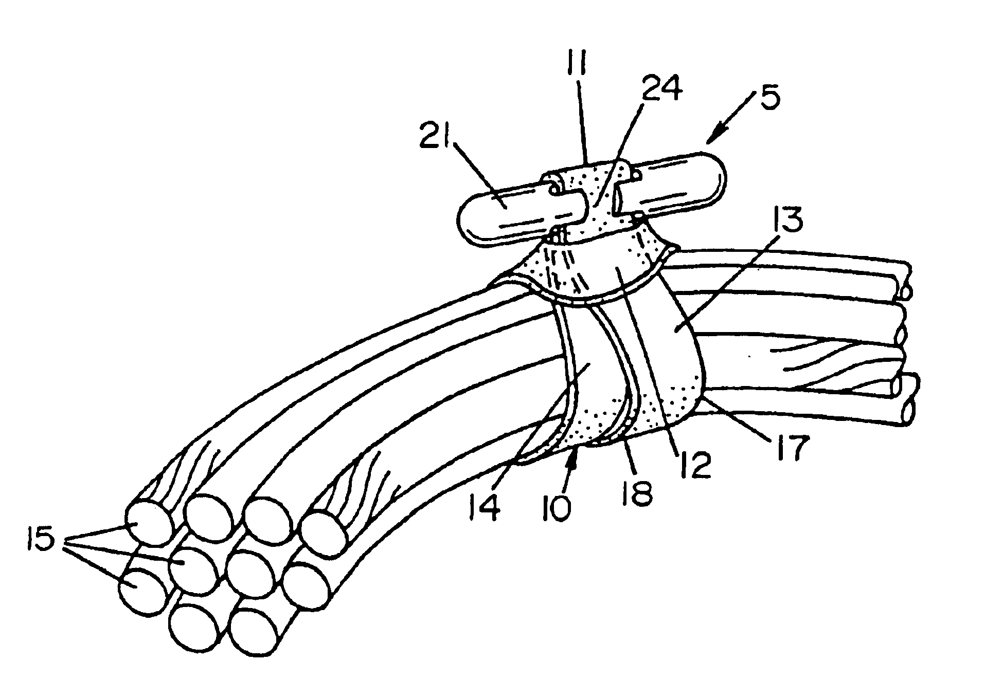
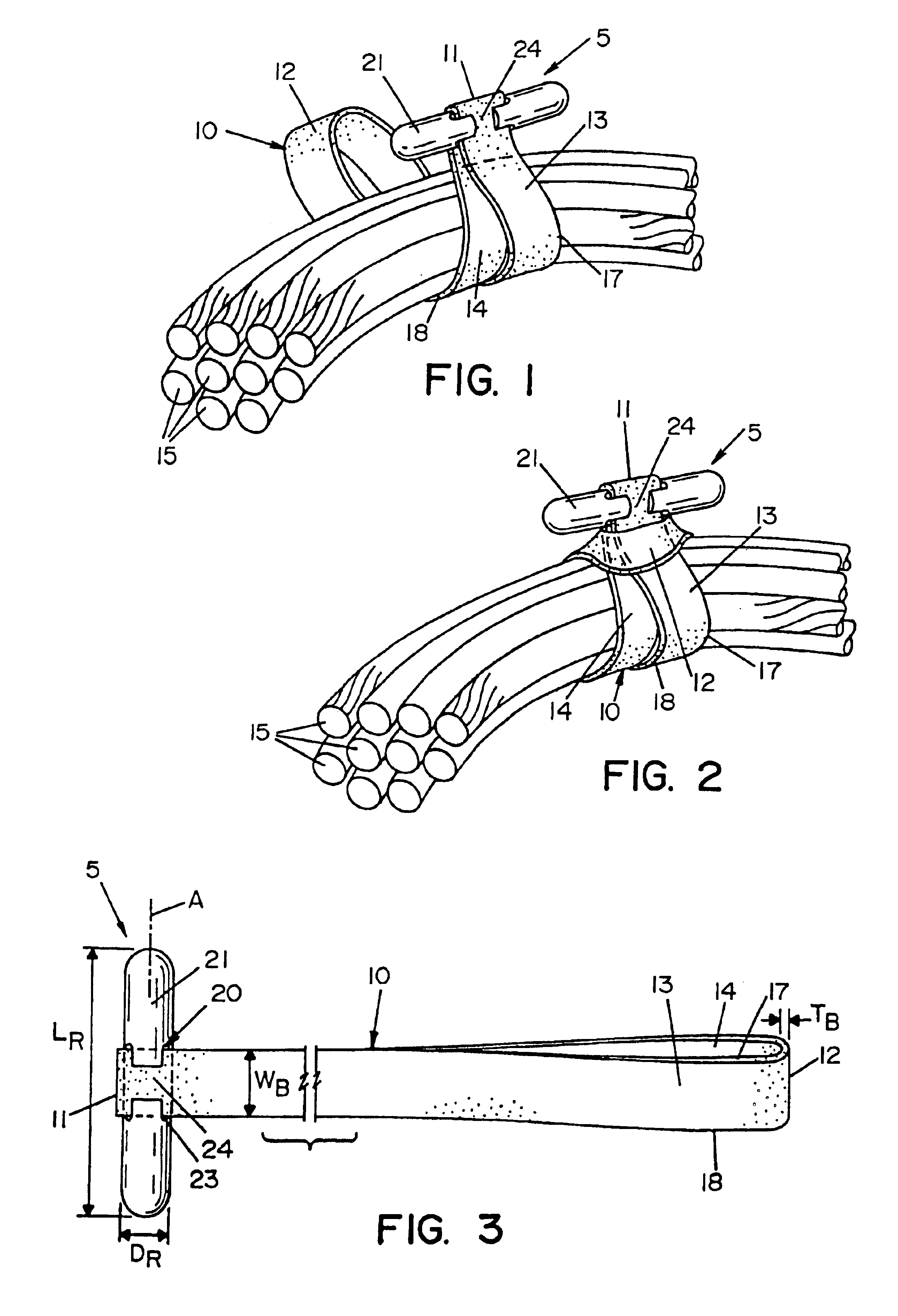
A rubber band retainer according to the concepts of the present invention is depicted in the Figures where it is generally referred to by the numeral 5. In FIG. 1, retainer 5 is shown attached to an elastomeric band, generally indicated by the numeral 10, having a first end 11 and a second end 12 and first and second sides 13, 14 extending between the first and second end 11, 12 forming a continuous band of material. Elastomeric bands of this configuration are commonly made of a variety of elastomeric compounds in a wide variety of different sizes.

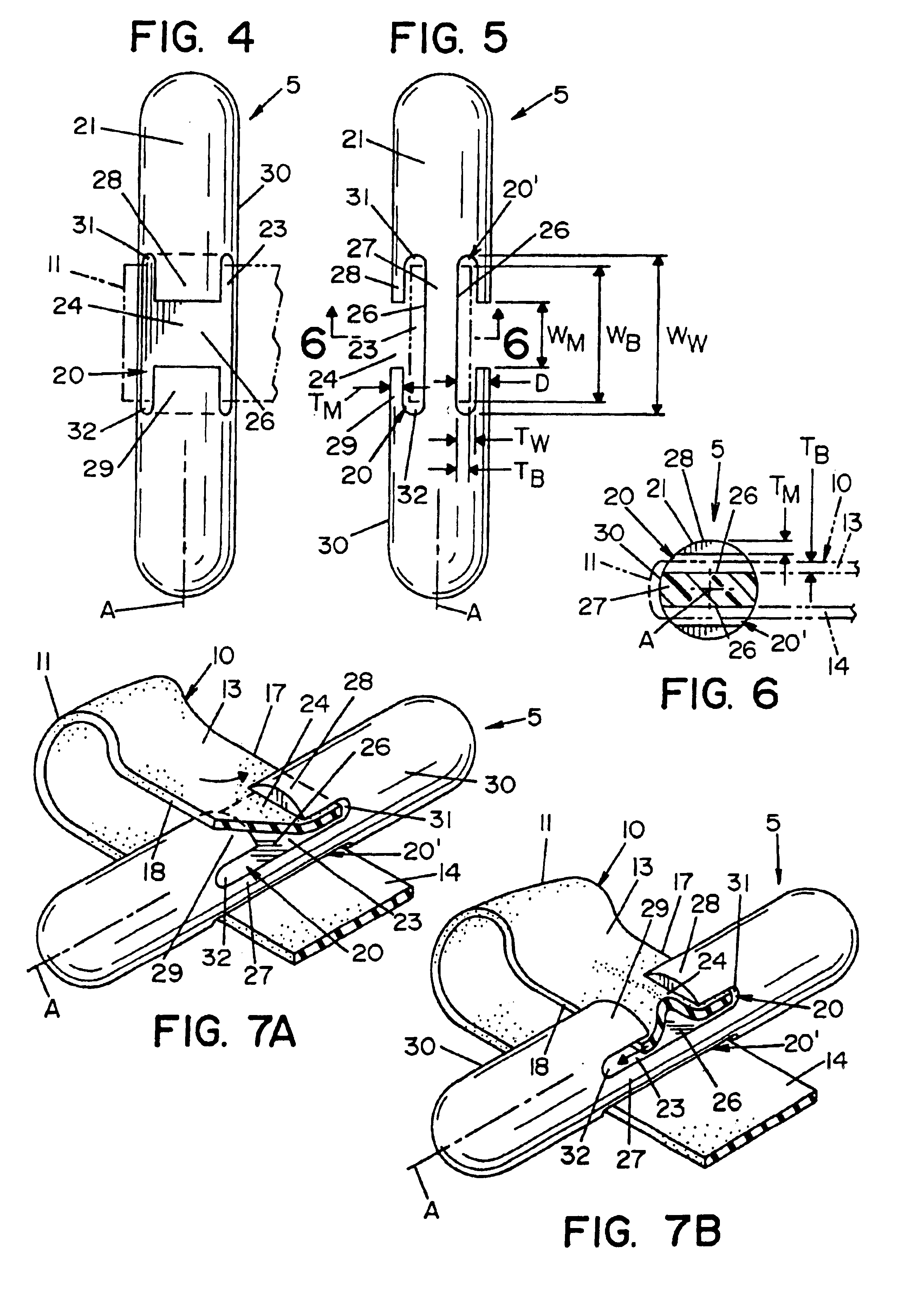
As shown in FIG. 1, retainer 5 may be attached to one end, in this case first end 11 of band 10. As depicted in FIGS. 7A and 7B, the retainer 5 is attached to band 10 by inserting first and second edges 17, 18 of band 10 sequentially or simultaneously into a retaining notch 20 formed in retainer 5. The free end of band 10, in this case second end 12, may be wrapped around one or more objects 15, such as the several cylindrical strands of m...


PUM


Abstract

A wrap for securing objects having an elastomeric band, a retainer having a body defining a notch for receiving widthwise a portion of the elastomeric band, a band receiving portion of the notch, a first tab extending axially over the band receiving portion of the notch and defining a mouth portion of the notch, wherein the mouth portion has a width less than the width of the elastomeric band.

Description

TECHNICAL FIELDThe present invention generally relates to a rubber band retaining apparatus. More specifically, the invention relates to a rubber band retainer which selectively joins end loops in a rubber band positioned about one or more objects. More particularly, the present invention relates to a rubber band retainer which attaches to an end loop of a rubber band for insertion through a second end loop of the rubber band when wrapped around one or more objects.BACKGROUND OF THE INVENTIONElastomeric bands have long been employed to bundle or otherwise organize one or more objects. Typically, these bands are used to organize objects such as: computer cables and cords, telephone system cords, power tool cords, building materials, automotive parts, jumper cables, gardening stakes, plants, appliance cords, extension cords, decorative lights, skies and poles, fishing equipment, boating lines, camping equipment and sleeping bags. The most common use of such bands is to stretch the ban...

Claims


Application Information

Patent Timeline
Patent Type & Authority Patents(United States)
IPC IPC(8): F16L3/22F16L3/233
CPCF16L3/233Y10T24/4745Y10T24/14Y10T24/15Y10T24/314
Inventor SMITH, KENNITH
Owner ALLIANCE RUBBER COMPANY
Learn More