Transonic hull and hydrofield (part III)

a transonic hull and hydrofield technology, applied in special-purpose vessels, vessel construction, vessel movement reduction by foils, etc., can solve the problems of inability to meet the needs of th, so as to improve the performance and maneuverability of the transonic hull, the effect of good efficiency

Inactive Publication Date: 2005-01-18
ALVAREZ CALDERON F ALBERTO
View PDF7 Cites 11 Cited by
  • Summary
  • Abstract
  • Description
  • Claims
  • Application Information

AI Technical Summary

Benefits of technology

The present invention specifies new unique design shapes, features, and methods of operation which qualitatively improve and extend the scope of the transonic hull TH and the transonic hydrofield TH inventions of patent application Ser. Nos. 08 / 814,418 and 08 / 814,017. The scope of the present invention is summarized below:1. An extension of the operational speed envelope of TH over a very broad speed range increase by means of new design characteristics and new hydrodynamic regimes beyond the previous subcritical and supercritical regimes in the displacement modes, namely: the hypercritical, the transplanar, and the x-regimes. With these improvements, a single TH hull can operate with good efficiency over a large speed spectrum which otherwise would require two or three ships with different conventional hulls; for example, a conventional displacement ship at lower range of speed and a vee-bottom or semi-planing hull for higher speeds.2. Another important feature of the invention pertains to hull characteristics and shapes above and below calm-water waterplane which are critical to permit successful operation over the broad speed regime in adverse seas, preferably also in optional combination with special longitudinal distribution of heavy mass components inside the hull, such as engines, fuel, and weapons.3. A third feature of the invention pertains to special shapes, trim, balance, center of gravity location, location of longitudinal center of flotation, and various kinds of flaps and streaks needed to make feasible and enhance and improve the performance and maneuverability of the transonic hull in calm water and adverse seas.4. Additionally, other important features of the invention are its hull shapes which have inherent low detectability by radar and other sensors, as well as a wake of low visibility and thermal content, which yields stealth properties to the hull which are nevertheless compatible with efficient hydrodynamics and good behavior in adverse seas.

Problems solved by technology

The deep stern drafts with broad beams at the stern are extremely inefficient.
Moreover, such prior art does not consider the effects of CB and CG location on drag under forward motion.
In respect to proximity of CG, CB, and LCF, I have discovered that their proximity as in conventional hulls is not viable for TH, because it renders this type of hull with unstable tendencies in pitch under fast motion, when subjected even to a minor pitch disturbance.
In a ship, such oscillations not only increase drag, but are undesirable for structures, for cargo and for passengers, and may be dangerous.
Such fundamental problems are serious.

Method used


Image

  • Transonic hull and hydrofield (part III)
  • Transonic hull and hydrofield (part III)
  • Transonic hull and hydrofield (part III)

Examples


Embodiment Construction

The nature and scope of the present invention can be better understood by reviewing the principal characteristics of conventional hulls, which have certain serious inherent problems in calm water and in an adverse sea, and examining also the limits and potential of transonic hulls TH and their hydrofields in patent application Ser. Nos. 08 / 814,418 and 08 / 814,417, all which sets the conceptual inquiry solved by the present invention.

I. Characteristics and Problems of Conventional Hulls.

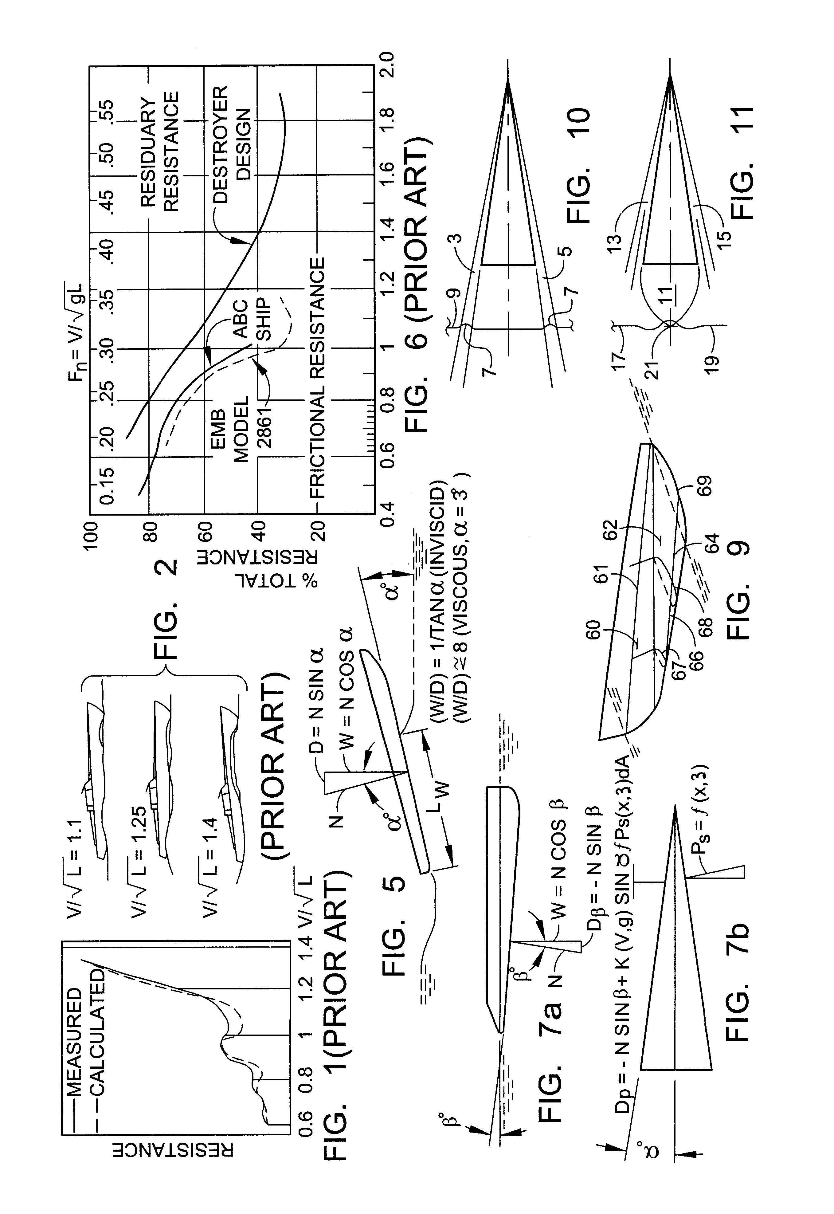
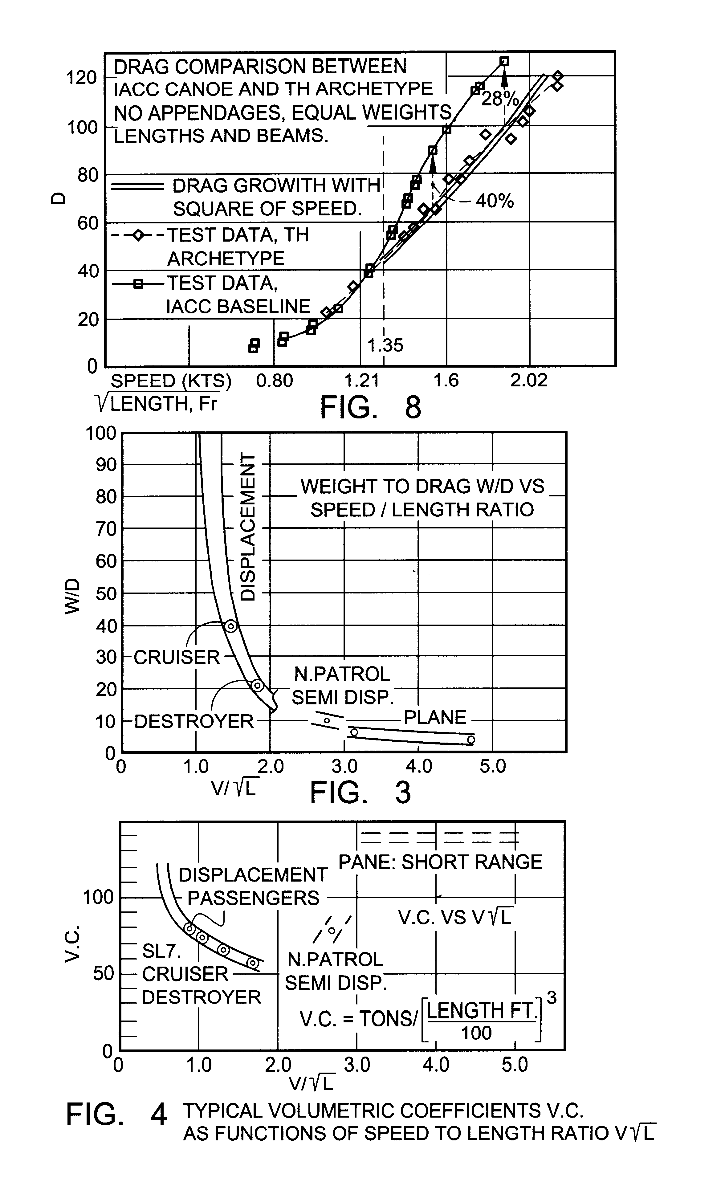
It is necessary for this review to separate the conventional hull designs by hull types in accordance to their operational speed envelopes. The envelopes are expressed for each hull type in terms of weight-to-drag ratios as function of speed-to-length ratios, best considered together with their corresponding volumetric coefficients, which are indicative of longitudinal surface and volume distributions responsive to their speed envelopes.

1a. Displacement Hulls.

Displacement hulls sustain boat weight by b...


PUM


Abstract

A transonic hull having a bow, a stern, a longitudinal length therebetween, side surfaces extending from the bow to outboard portions of the stern, a lower surface extending between the side surfaces, the transonic hull having a submerged volume with an approximately triangular shape in planview with apex adjacent the bow and a base adjacent the stern, and an approximately triangular shape in side view when in motion with a base adjacent the bow and an apex adjacent the stern.

Description

BACKGROUND OF THE INVENTION1. Technical FieldThe present invention pertains to water-supported vessels such as commercial and military ships, submersibles, yachts, hulls for seaplanes operating in and out of surface effects, and boats in general, including operation of such vessels at high speeds in adverse seas.2. Description of the Prior ArtThe art related to the present application covers all the art cited by Examiner in application Ser. Nos. 08 / 814,418 and 08 / 814,417, as well as the art cited by the inventor during the prosecution of application Ser. Nos. 08 / 814,418 and 08 / 814,417. It may also relate to the art in Jane's High Speed Marine Craft. In addition, the art related to the present application may include the Transonic Hull (TH) and Transonic Hydrofield (TH) specified in patent application Ser. No. 08 / 814,418, and the propulsion, controls, and shapes of Transonic Hulls specified in patent application Ser. No. 08 / 814,417.Although certain vessels having triangular hull plan...

Claims


Application Information

Patent Timeline
Patent Type & Authority Patents(United States)
IPC IPC(8): B63B39/00B63B1/00B63B39/06B63B1/04
CPCB63B39/061B63B1/04
Inventor ALVAREZ-CALDERON F., ALBERTO
Owner ALVAREZ CALDERON F ALBERTO
Why Eureka
Try Eureka