
System and method for autonomously performing a downhole well operation

a technology of autonomous operation and well tool, which is applied in the direction of survey, borehole/well accessories, sealing/packing, etc., can solve the problems of requiring significant equipment and manpower, affecting the completion of the well, and causing the well to be crushed

Inactive Publication Date: 2005-01-18
BAKER HUGHES INC
View PDF9 Cites 80 Cited by
  • Summary
  • Abstract
  • Description
  • Claims
  • Application Information

AI Technical Summary

Benefits of technology

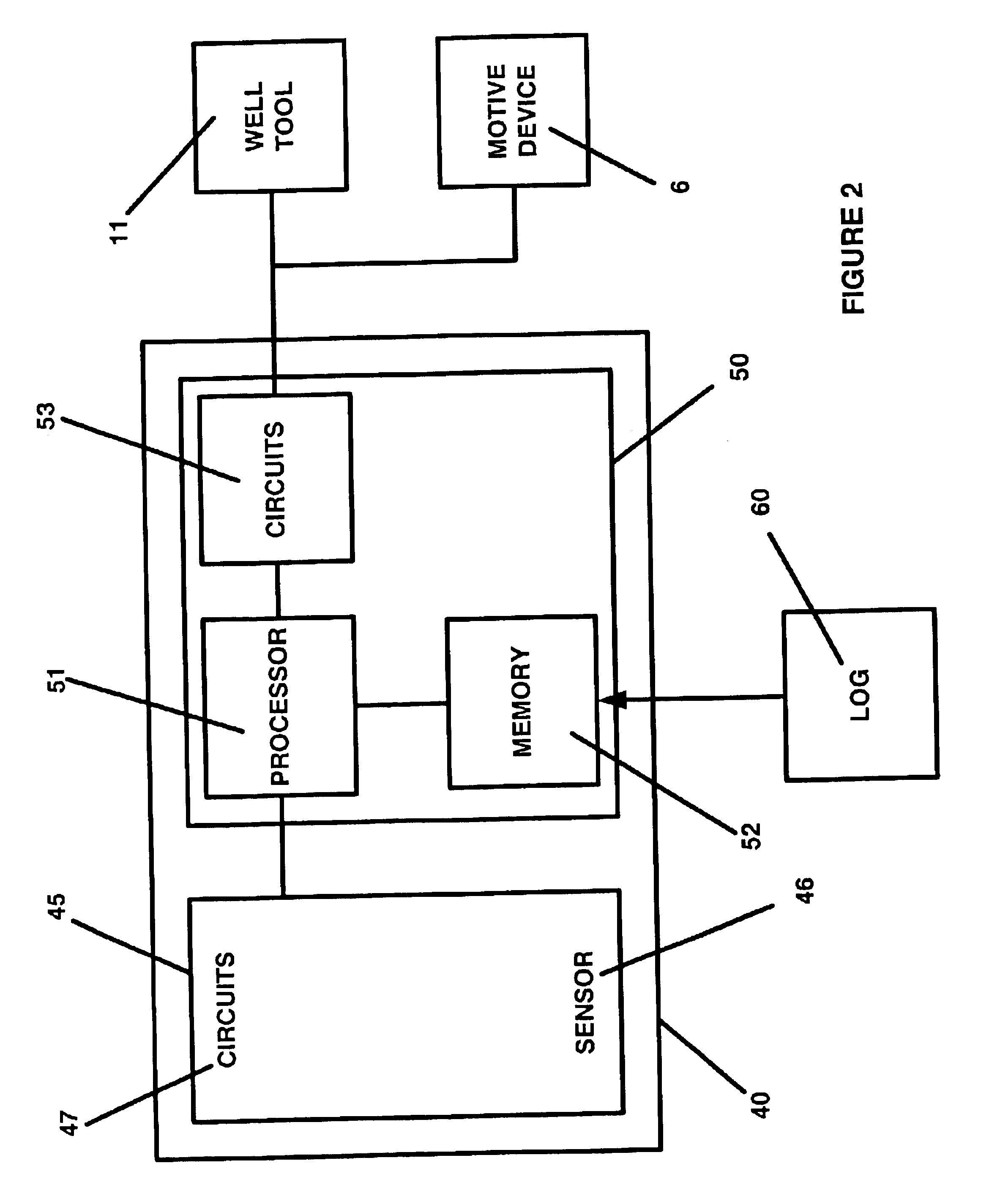
In one embodiment of the present invention, an autonomous system is provided for operating a well tool proximate a predetermined location in a wellbore. The system comprises a tool string having at least one well tool for performing at least one well operation in the wellbore; a motive device for causing the tool string to traverse the wellbore; and a control system adapted to position the tool string proximate the predetermined borehole location. The control system contains at least one sensor for detecting mass irregularities caused by downhole production elements including but not limited to casing collars; bridge plugs; collar stops; safety valves; and packers. The sensor may also detect mass irregularities caused by perforated casing. The control system also has a processor system with a processor and a memory for storing at least one well log into the memory in the autonomous system. The control system compares the sensor signals to the well log to locate the tool proximate the predetermined downhole location. The control system also controls the operation of the motive device and the well tool.
Another preferred embodiment of the present invention is a method for autonomously performing a well operation proximate a predetermined location downhole. The method comprises storing a well log in a memory of a processor in a control system in a tool string. The tool string is traversed through the wellbore under autonomous control of the control system. At least one parameter of interest is sensed in the wellbore and a signal related thereto is generated. The sensed signal is compared to the stored well log to identify the predetermined location in the wellbore. The well tool is operated under autonomous control of the control system proximate the predetermined location.
Another aspect of the present invention is

Problems solved by technology

Although modern oil and gas well production has progressed to a fine art, a variety of difficult problems may still be encountered during well completion, production, servicing and rework and it is often necessary to precisely locate one or more of the casing pipe joints or other downhole elements in a well.
Typical problems requiring correction within a well are: crushed regions in the tubing, sand bridges or accumulation of paraffin, scale, rust or other debris.
Each of the deployment techniques mentioned require significant equipment and manpower to deploy the tool in the wellbore.

Method used


Image

  • System and method for autonomously performing a downhole well operation
  • System and method for autonomously performing a downhole well operation
  • System and method for autonomously performing a downhole well operation

Examples


Embodiment Construction

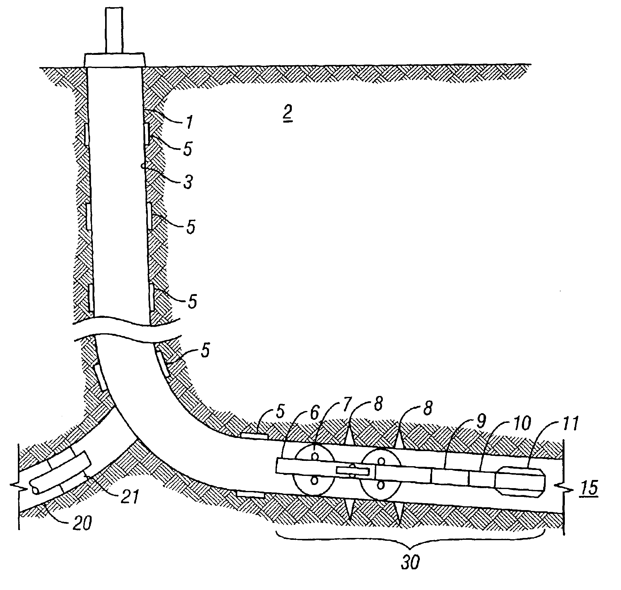
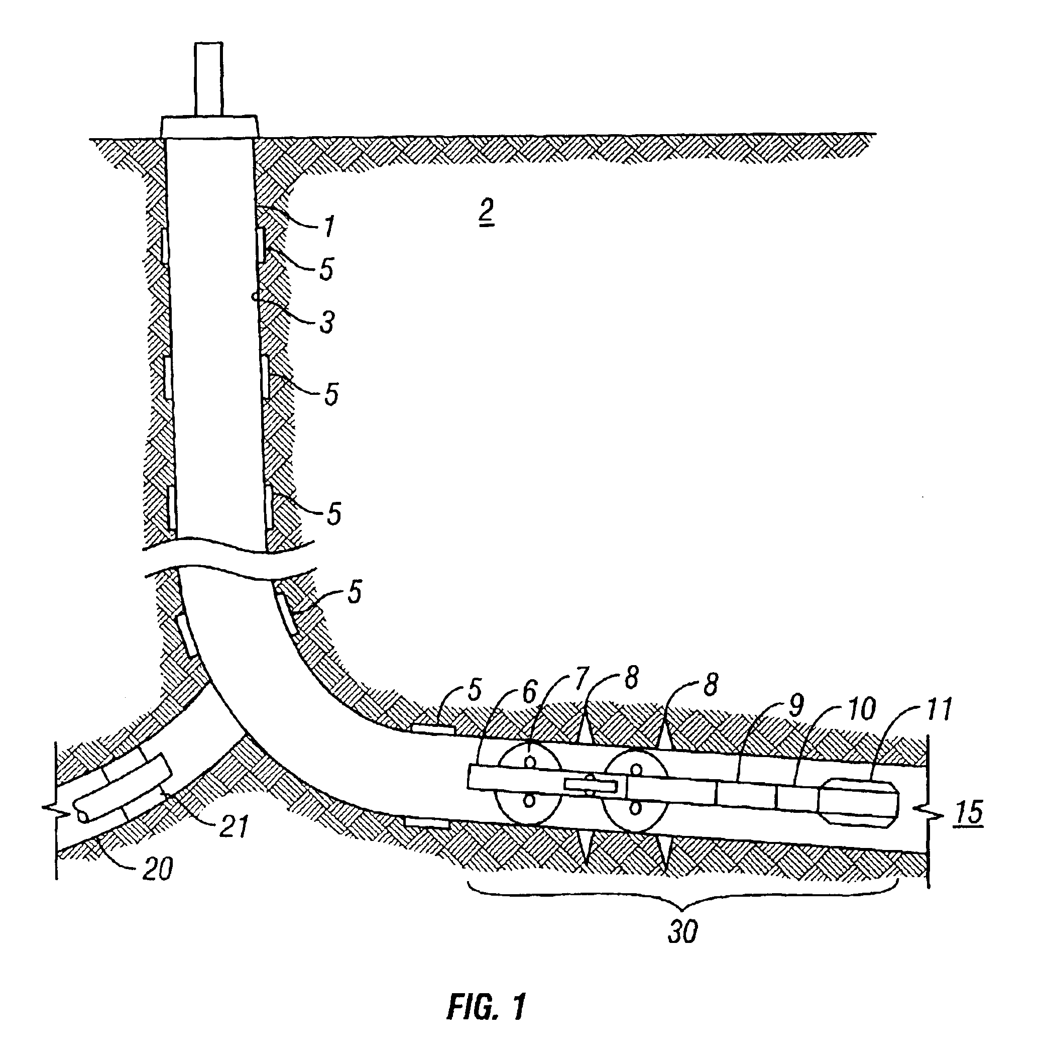
In FIG. 1, according to one preferred embodiment, a wellbore 1 is schematically illustrated penetrating a subterranean formation 2. The wellbore 1 is completed with a casing string 3 in the usual manner. The casing string comprises multiple sections of pipe joined together by casing collars 5 at each joint. The wellbore 1 is shown with a deviated bottom hole section 15 which is not uncommon. However, the system described herein is also suitable for use in essentially vertical wellbores as well. Also shown in FIG. 1 is a lateral takeoff wellbore 20 which is completed with a packer 21. Such multiple takeoffs are becoming common in drilling. The casing collars 5 and other downhole equipment such as packer 21 create mass irregularities compared to the relatively uniform mass of the casing 3. Perforations 8 also create mass irregularities by removing mass from the casing. During the casing and completion of the well, these mass irregularities are logged typically using electromagnetic se...


PUM


Abstract

An autonomous system for performing a well operation at a predetermined location in a wellbore comprises a tool string having at least one well tool, a motive device for traversing the wellbore, and a control system adapted to position the tool string near the predetermined location. The control system comprises (i) a sensing system for detecting mass irregularities in the wellbore and (ii) a processor system having a processor with memory for storing at least one well log. The processor acts under programmed instructions to compare sensor signals to the stored well log to determine a tool string position in the wellbore. The control system also contains circuits for controlling the operation of the well tool and the motive device.

Description

BACKGROUND OF THE INVENTION1. Field of the InventionThe present invention relates generally to subterranean well completion, servicing, and rework and more particularly to an autonomous system for operating a well tool in a wellbore for purposes of completion, servicing, and rework.2. Description of the Related ArtIn the drilling and completion of oil and gas wells, a wellbore is drilled into a subsurface producing formation. Typically, a string of casing pipe is then cemented into the wellbore. An additional string of pipe, commonly known as production tubing, may be disposed within the casing string and is used to conduct production fluids out of the wellbore. The downhole string of casing pipe is comprised of a plurality of pipe sections which are threadedly joined together. The pipe joints, also referred to as collars, have increased mass as compared to the pipe sections. After the strings of pipe have been cemented into the well, logging tools are run to determine the location ...

Claims


Application Information

Patent Timeline
IPC IPC(8): E21B44/00E21B47/00E21B23/00
CPCE21B44/005E21B47/00E21B2023/008E21B23/001E21B23/00E21B33/10E21B34/10E21B43/119
Inventor MACKENZIE, GORDON R. J.
Owner BAKER HUGHES INC
Learn More