Variable trailing edge geometry and spanload control

a technology of trailing edge geometry and spanload control, which is applied in the direction of automatic actuation, canard-type aircraft, and efficient propulsion technologies, etc., can solve the problems of increasing drag when operating outside the normal operating speed, not efficient for optimizing the wing span load distribution, and not being able to achieve the optimal angle of operation

Inactive Publication Date: 2005-01-18
THE BOEING CO
View PDF18 Cites 60 Cited by
  • Summary
  • Abstract
  • Description
  • Claims
  • Application Information

AI Technical Summary

Problems solved by technology

Ailerons and flaps are typically a significant percentage (i.e., approximately 15% and 35%, respectively), of an aircraft wing chord (the forward to aft length of a wing), and limited in spanwise extent so are therefore not efficient for optimizing wing span load distributions during flight to maximize aircraft performance.
The use of these devices, however, results in increased drag when operating outside the normal operating speed, because the fixed angle that the device makes from the plane of the trailing edge of the wing is optimized for the normal cruise speed, and therefore provides a less than optimum angle for operation at other than normal cruise speeds.
The disadvantage of this design is the tradeoff between the additional weight required for the additional mechanical devices to modify the wing shape with the increased efficiency of the wing.

Method used


Image

  • Variable trailing edge geometry and spanload control
  • Variable trailing edge geometry and spanload control
  • Variable trailing edge geometry and spanload control

Examples


Embodiment Construction

The following description of the preferred embodiment(s) is merely exemplary in nature and is in no way intended to limit the invention, its application, or uses. Reference to use on an aircraft wing is generally made herein, however, the invention is not limited to aircraft or wing use.

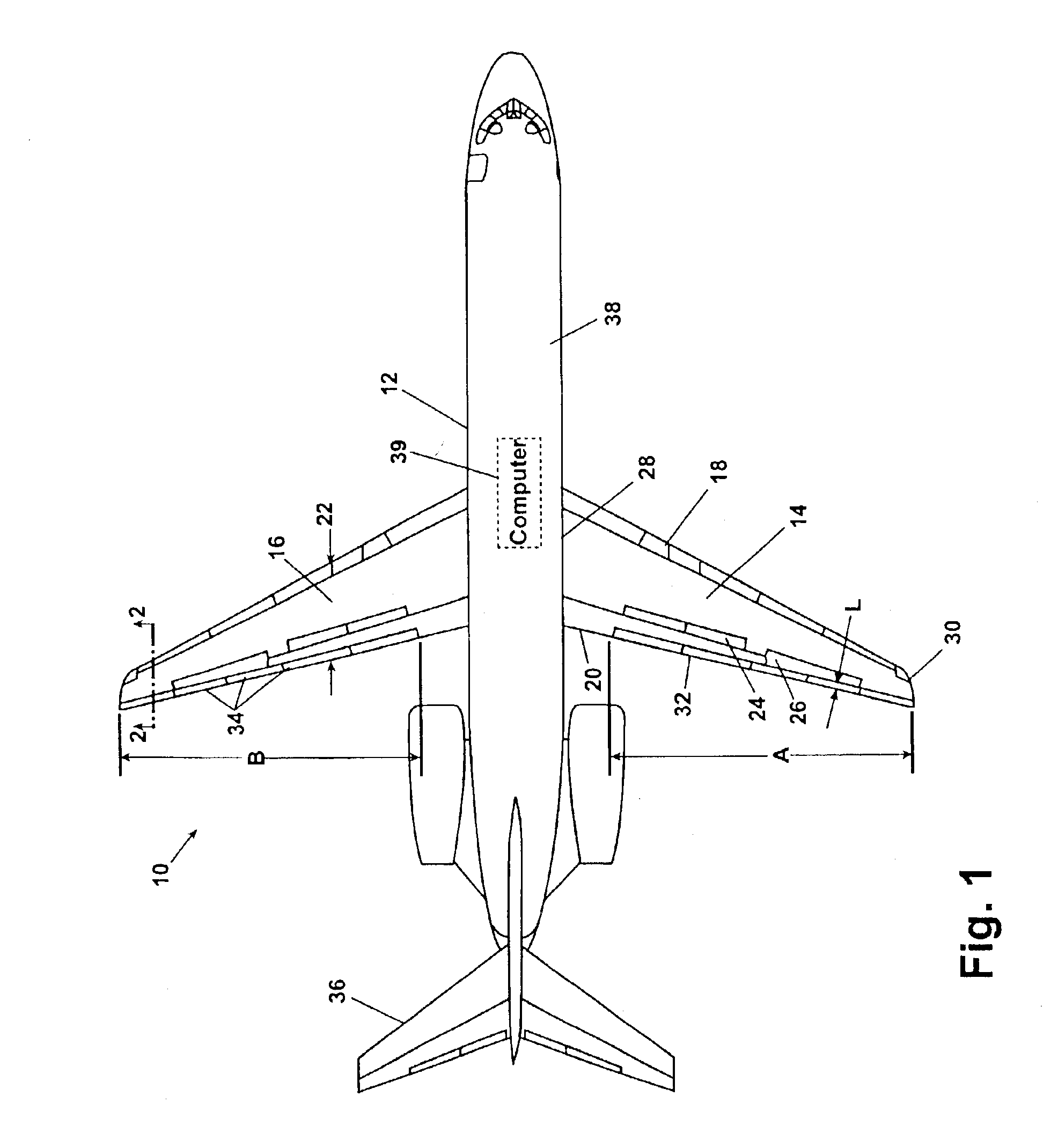
Referring to FIG. 1, a variable trailing edge system 10 in accordance with a preferred embodiment of the present invention is shown. An aircraft 12 includes a starboard wing 14 and a port wing 16. Each of the wings include a leading edge 18 and a trailing edge 20. A chord length 22 is identified for the port wing 16, but is common to either wing. A plurality of chord lengths 22 can exist for a given wing because the chord length 22 is determined at a cross section taken through the wing, and the tapering wing design of many commercial aircraft (such as the 2-engine design shown in FIG. 1) provides a changing cross section as the wing tapers down in length from the inboard end to the outboard end. Com...


PUM


Abstract

A mobile platform lift increasing system includes at least one wing-shaped structure having a leading edge, a trailing edge and a chord length perpendicularly measurable between the leading and trailing edges. A rotatable control surface is located near a trailing edge undersurface. The control surface length is approximately one to five percent of the chord length. A deployment device is positioned between the wing shaped structure and the control surface. The deployment device operably rotates the control surface through a plurality of positions ranging between an initial position and a fully deployed position. Wing lift is increased at speeds up to approximately transonic speed by continuously rotating the control surface to accommodate variables including mobile platform weight change from fuel usage.

Description

FIELD OF THE INVENTIONThe present invention relates generally to lift producing aerodynamic surfaces and more specifically to the trailing edge geometry of lift producing aerodynamic surfaces.BACKGROUND OF THE INVENTIONThe lift producing structures such as wings, winglets, horizontal tails, canards etc. (hereinafter referred to as “wings”) for an aircraft or any mobile platform, commonly have an airfoil shape which includes a rounded nose, a relatively thick forward cross section, a tapering section, and a relatively thin trailing edge cross section. Aircraft wings commonly include ailerons and / or flaps to modify airflow over the wing to change the aircraft attitude or to increase lift for take-off and landing procedures, respectively. Ailerons and flaps are typically a significant percentage (i.e., approximately 15% and 35%, respectively), of an aircraft wing chord (the forward to aft length of a wing), and limited in spanwise extent so are therefore not efficient for optimizing wi...

Claims


Application Information

Patent Timeline
Patent Type & Authority Patents(United States)
IPC IPC(8): B64C9/00B64C39/12B64C39/00B64C3/00B64C3/50B64C3/58
CPCB64C3/50B64C3/58B64C9/00B64C39/12Y02T50/44Y02T50/12Y02T50/145Y02T50/32B64C2003/145Y02T50/30Y02T50/40Y02T50/10
Inventor VASSBERG, JOHN CHARLESGREGG, III, ROBERT D.
Owner THE BOEING CO
Why Eureka
Try Eureka