Missing nozzle detection method and sensor for an ink jet printer

a detection method and sensor technology, applied in the field of ink jet printers, can solve the problems of easy clogging of the nozzle easy clogging of the ink jet printhead, etc., and achieve the effects of low cost, less cost of the sensor, and high quality perception

Inactive Publication Date: 2005-01-18
FUNAI ELECTRIC CO LTD
View PDF35 Cites 26 Cited by
  • Summary
  • Abstract
  • Description
  • Claims
  • Application Information

AI Technical Summary

Benefits of technology

An advantage of the present invention is that malfunctioning nozzles are detected and compensated for such that the malfunctioning nozzles are transparent to the user and quality perception remains high.
Another advantage is that the cost of the sensor is much less than that of a reflective, optical-type sensor. The sensing circuit requires just a few low cost components.
Yet another advantage is that only a rough alignment of the sensor in the printer is required for ease of printer manufacturing assembly.

Problems solved by technology

Ink jet printhead nozzles are prone to clogging due to dried ink or debris physically impeding the nozzle plate orifice, or due to electrical failure, such as non-functional heater resistors that have failed due to electrostatic discharge, manufacturing defect on the silicon chip, broken TAB bond or chip trace connections, etc.
Even though the printhead ships from the factory with all nozzles testing good, defects including those listed above can occur in shipping, installation, or use of the head.
While a head with such a defect is generally still usable, the resultant print quality defects are readily apparent to the user in the form of white lines in the printed pages.
This is both a nuisance and a very visible negative contributor to the user's perception of the printer's quality.
The drawbacks of the known schemes are that they require fairly expensive circuitry and / or special optical sensors to be used.

Method used


Image

  • Missing nozzle detection method and sensor for an ink jet printer
  • Missing nozzle detection method and sensor for an ink jet printer
  • Missing nozzle detection method and sensor for an ink jet printer

Examples


Embodiment Construction

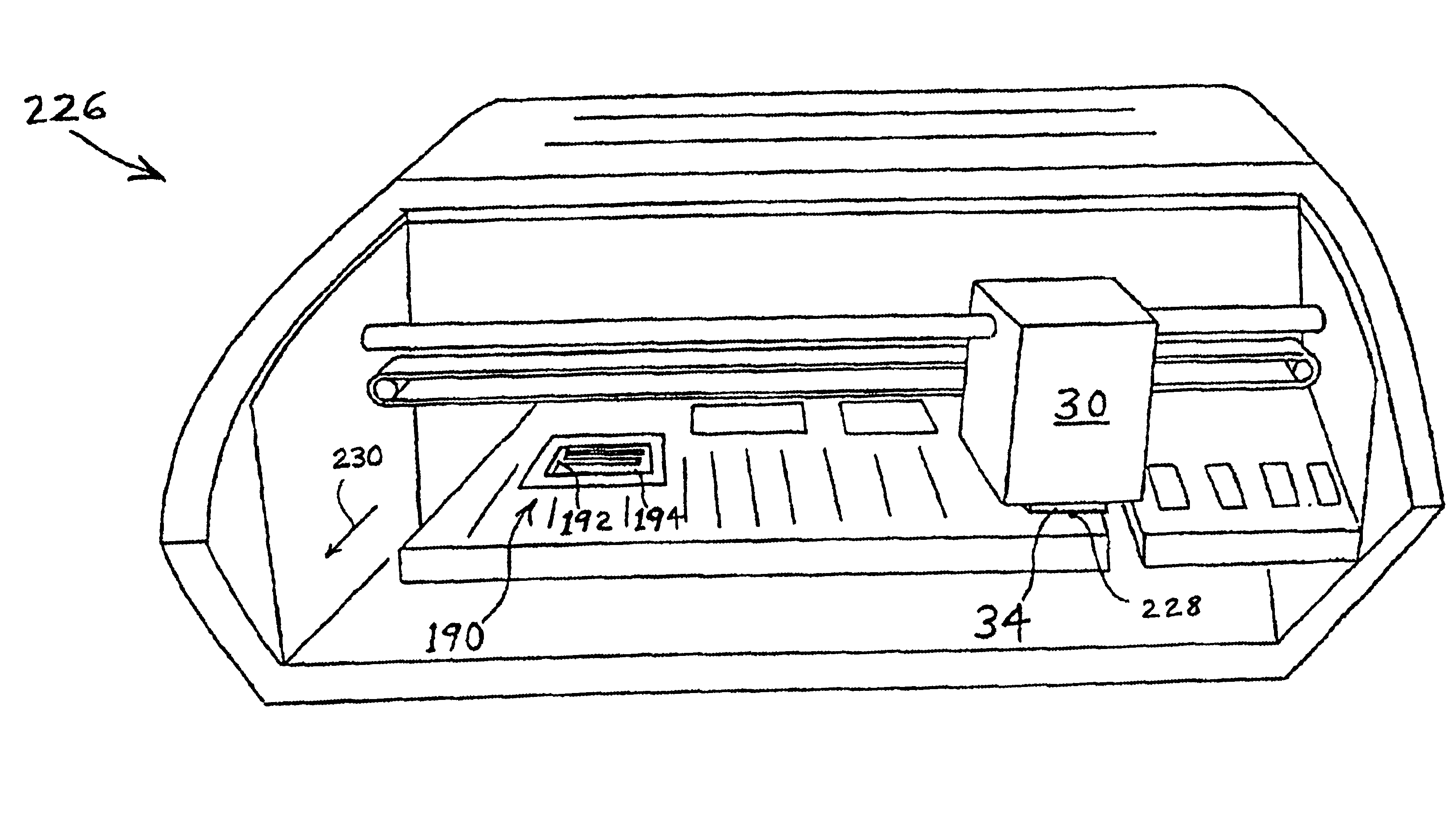
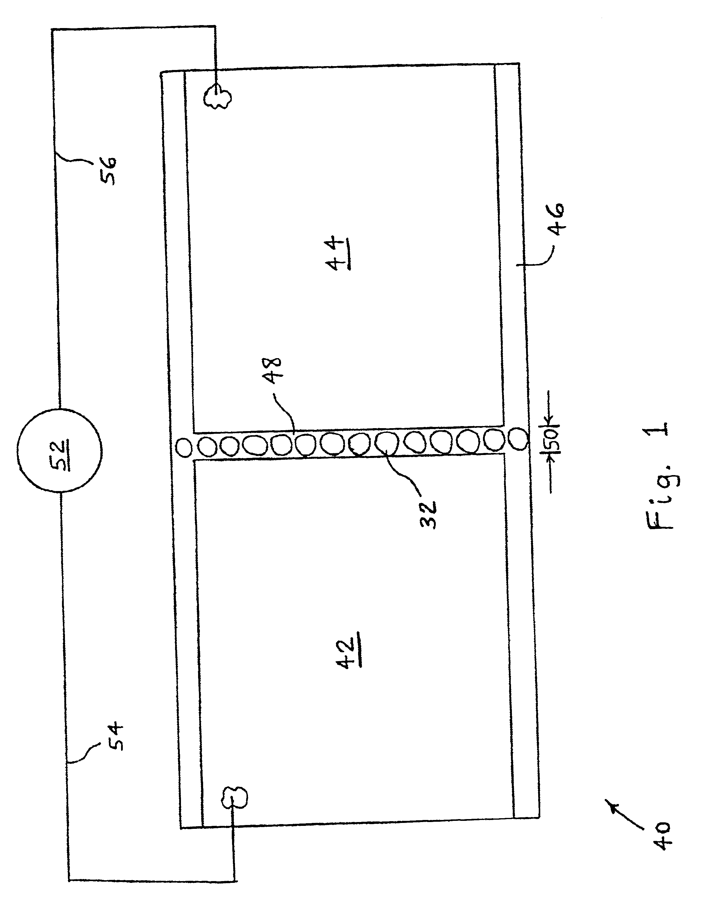
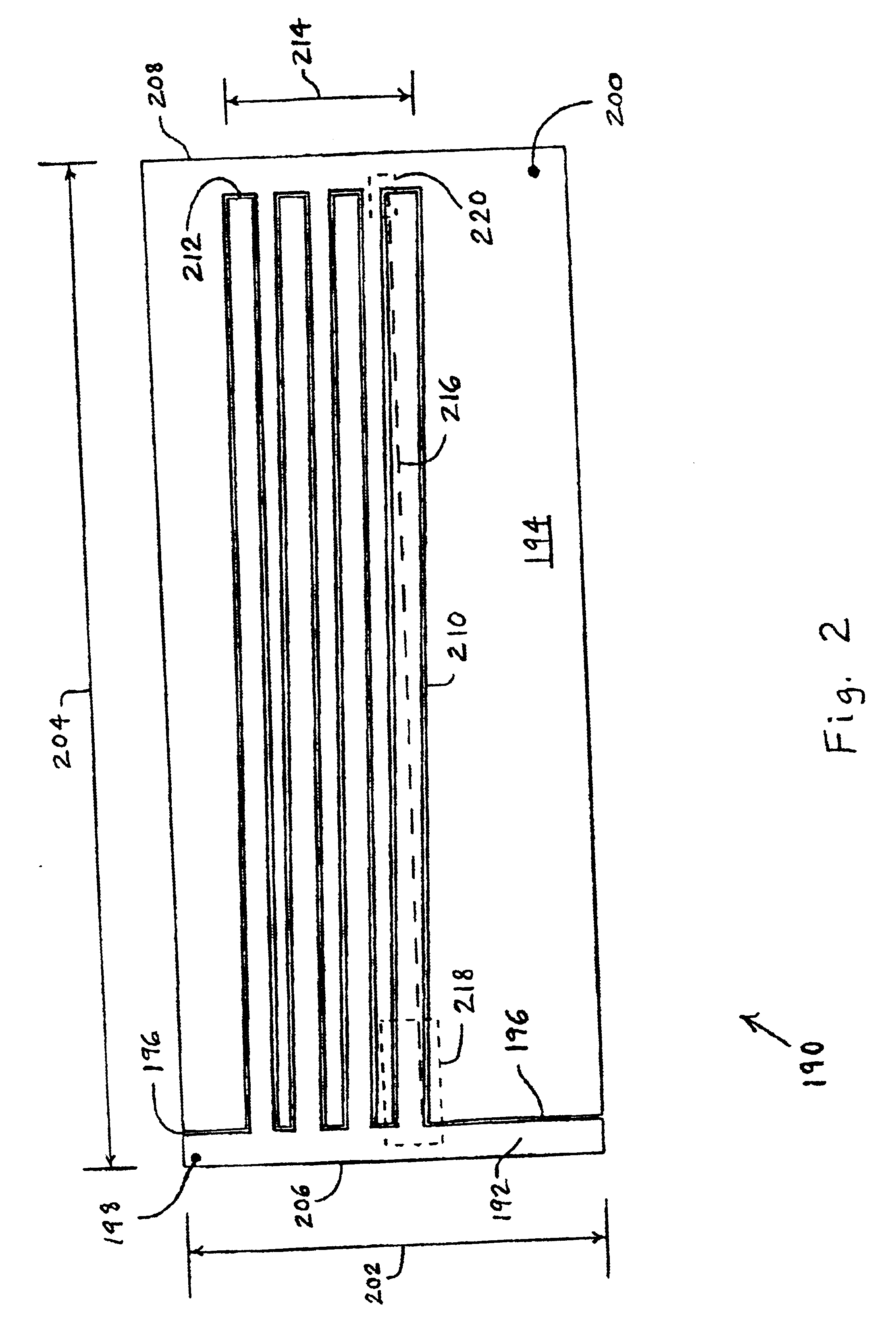
Referring now to the drawings and particularly to FIG. 1, there is shown one embodiment of a slotted sensor 40 of the present invention, including two copper terminals 42, 44 on a mylar substrate 46. Terminals 42, 44 are separated by a gap 48 having a width 50 of approximately between {fraction (1 / 1200)}-inch and {fraction (1 / 600)}-inch, which is approximately the width of an ink droplet 32. Gap 48 can be formed by laser cutting. An ohmmeter 52 has leads 54, 56 connected to terminals 42, 44, respectively, to measure the resistance therebetween. When no ink drops 32 are between terminals 42 and 44, the resistance between terminals 42 and 44 is many hundreds of megohms. If a single column of ink drop 32 is printed from a printhead into gap 48, as illustrated in FIG. 1, the resistance between terminals 42, 44 drops into the range of approximately between 0.5 and 3 megohms. Printing this column of ink drops 32 even one print element (pel) off-center of gap 48 leaves the resistance betwe...


PUM


Abstract

A method of detecting malfunctioning ones of a plurality of nozzles of a printhead in an ink jet printer includes providing a sensor having at least two terminals defining at least one gap therebetween. An attempt is made to jet ink from a first of the nozzles into the at least one gap. A resistance between at least two of the terminals is measured to determine whether the ink has been jetted into the at least one gap. The attempting and measuring steps are repeated for each remaining nozzle.

Description

BACKGROUND OF THE INVENTION1. Field of the InventionThe present invention relates to ink jet printers, and, more particularly, to a method and apparatus for checking the operation of the nozzles in an ink jet printer.2. Description of the Related ArtInk jet printhead nozzles are prone to clogging due to dried ink or debris physically impeding the nozzle plate orifice, or due to electrical failure, such as non-functional heater resistors that have failed due to electrostatic discharge, manufacturing defect on the silicon chip, broken TAB bond or chip trace connections, etc.Even though the printhead ships from the factory with all nozzles testing good, defects including those listed above can occur in shipping, installation, or use of the head. While a head with such a defect is generally still usable, the resultant print quality defects are readily apparent to the user in the form of white lines in the printed pages. This is both a nuisance and a very visible negative contributor to ...

Claims


Application Information

Patent Timeline
Patent Type & Authority Patents(United States)
IPC IPC(8): B41J29/393
CPCB41J29/393
Inventor ADKINS, CHRISTOPHER ALANAHNE, ADAM JUDEEDWARDS, MARK JOSEPH
Owner FUNAI ELECTRIC CO LTD
Why Eureka
Try Eureka