Illuminative universal joint

a universal joint and socket technology, applied in the field of socket wrenches, can solve the problem that the structure cannot fit in the open-ended wrench

Inactive Publication Date: 2005-01-18
CHEN TERENCE
View PDF5 Cites 14 Cited by
  • Summary
  • Abstract
  • Description
  • Claims
  • Application Information

AI Technical Summary

Problems solved by technology

This structure however does not fit in open-ended wrenches.

Method used


Image

  • Illuminative universal joint
  • Illuminative universal joint
  • Illuminative universal joint

Examples


Embodiment Construction

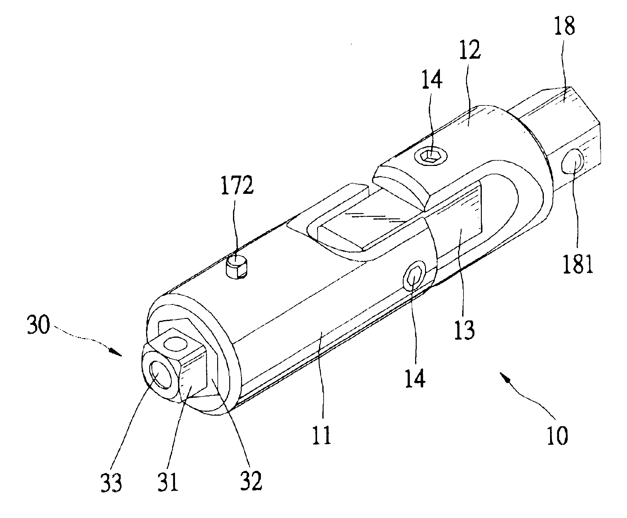
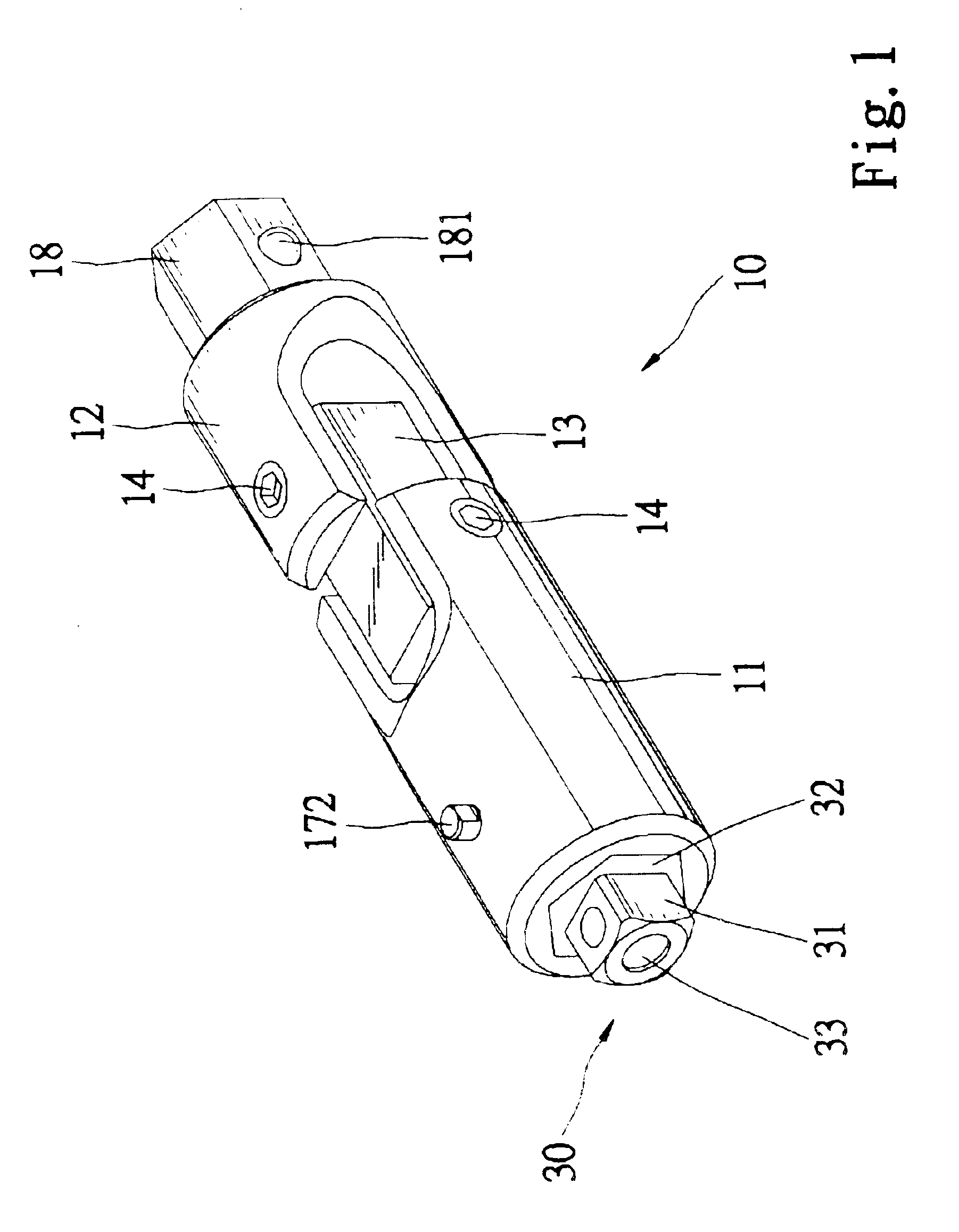
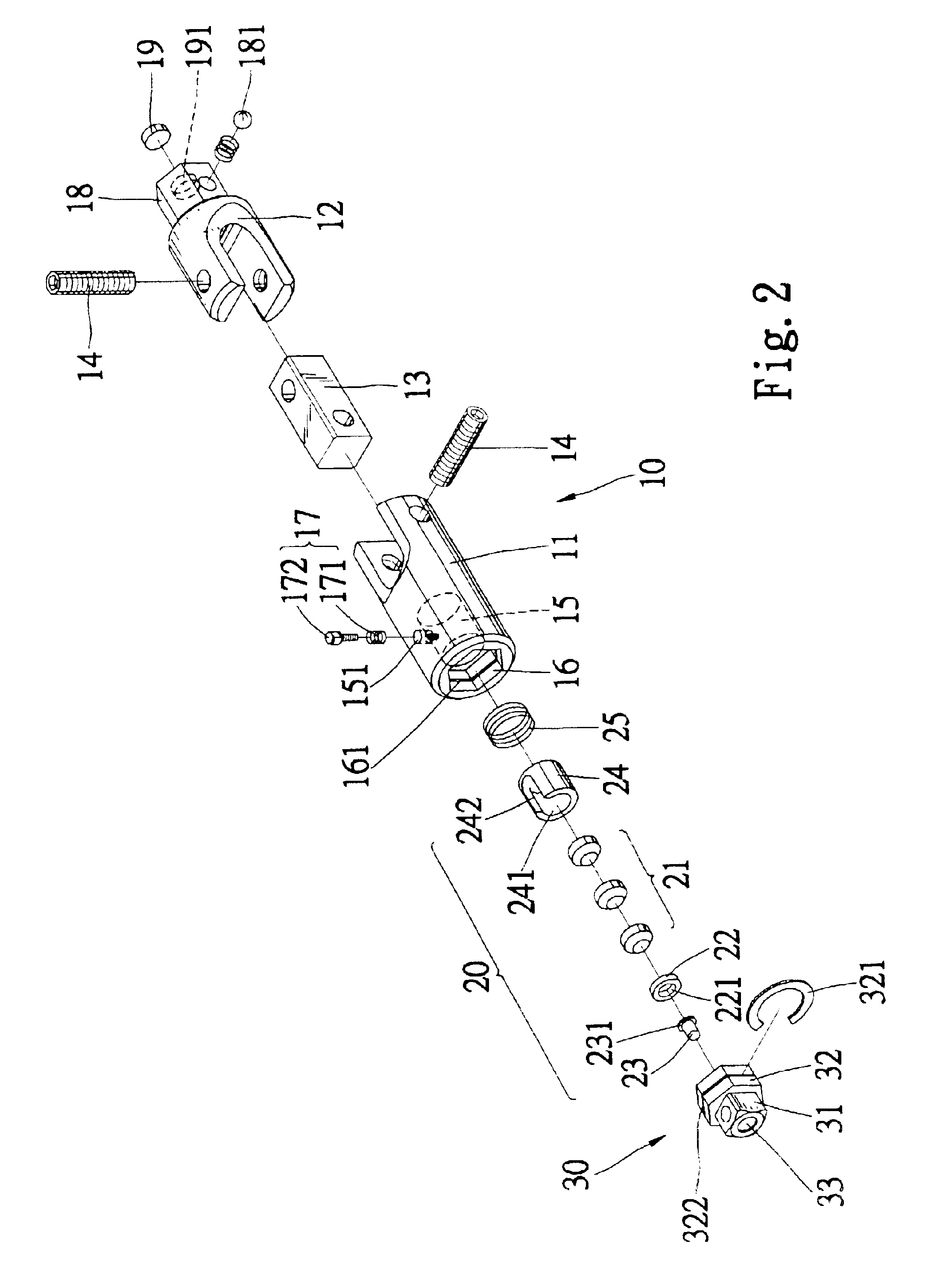
Referring to FIG. 1, according to the preferred embodiment of the present invention, an illuminative universal joint 10 includes a first element 12, a second element 11 and a third element 13 connected between the first element 12 and the second element 11. The first element 12 includes two tabs (not numbered) at an end and a hexangular insert 18 at an opposite end. The second element 11 includes two tabs (not numbered) at an end and a socket (not numbered) at an opposite end. The third element 13 is a square rod. The tabs of the first element 12 are pivotally connected with two sides of the third element 13 by means of a pin 14. The tabs of the second element 11 are pivotally connected with the other sides of the third element 13 by means of another pin 14.

Referring to FIG. 2, the hexangular insert 18 of the first element 12 defines a cavity 191 for receiving a magnet 19. A spring-biased ball detent 181 is installed at the hexangular insert 18.

The socket of the second element 11 in...


PUM


Abstract

An illuminative universal joint includes a first element, a second element, a third element connected between the first element and the second element, an illuminative device, a switch and a head. The first element is for engagement with a handle. The second element defines a space. The third element includes an end pivotally connected with the first element and an opposite end pivotally connected with the second element. The illuminative device is installed in the space for emitting light. The switch is mounted on the second element for turning on and off the illuminative device. The head includes a first insert fit in the space, a second insert for insertion into a tool bit and a hole defined therein for passing light.

Description

FIELD OF INVENTIONThe present invention relates to a socket wrench including a handle and a socket and, more particularly, to an illuminative joint between the handle and the socket.BACKGROUND OF INVENTIONTaiwanese Patent Publication No. 474237 discloses an illuminative device 30 of a socket wrench. The socket includes a socket 10 in which the illuminative device 30 is installed. The illuminative device 30 includes a light 31 and two batteries 38. The socket 10 defines a square hole 11 in an end and a hexangular hole 12 in an opposite end. The square hole 11 is for receiving a square insert 51 of the handle 50. The hexangular hole 12 is for receiving a hexangular insert of a selective one of several joints 20, 21 and 22. Each of the joints 20, 21 and 22 can be connected with sockets (not shown) for engagement with bolts. Each of the joints 20, 21 and 22 defines a hole 203 through which light can pass. This structure however does not fit in open-ended wrenches. Moreover, the light 31...

Claims


Application Information

Patent Timeline
Patent Type & Authority Patents(United States)
IPC IPC(8): B25B23/00B25B23/18B60Q3/06B60Q3/00
CPCB25B23/0014B60Q3/06B25B23/18B60Q3/30F16D3/38
Inventor CHEN, TERENCE
Owner CHEN TERENCE
Why Eureka
Try Eureka