Ultrathin-walled rolling bearing

Active Publication Date: 2005-01-18
NTN CORP
View PDF2 Cites 20 Cited by
  • Summary
  • Abstract
  • Description
  • Claims
  • Application Information

AI Technical Summary

Benefits of technology

An object of the present invention is to prevent or inhibit the production o

Problems solved by technology

Since resin-made segments constituting a cage are injection-molded articles, there are cases where the fitting in the convex-concave fit portion becomes loose due to an error in molding.
Further, the lead and delay of the rolling elements take place depending on the internal clearance of the bearing and the service conditions.
10), rather than all the segments being joined together, the lead a

Method used


Image

  • Ultrathin-walled rolling bearing
  • Ultrathin-walled rolling bearing
  • Ultrathin-walled rolling bearing

Examples


Embodiment Construction

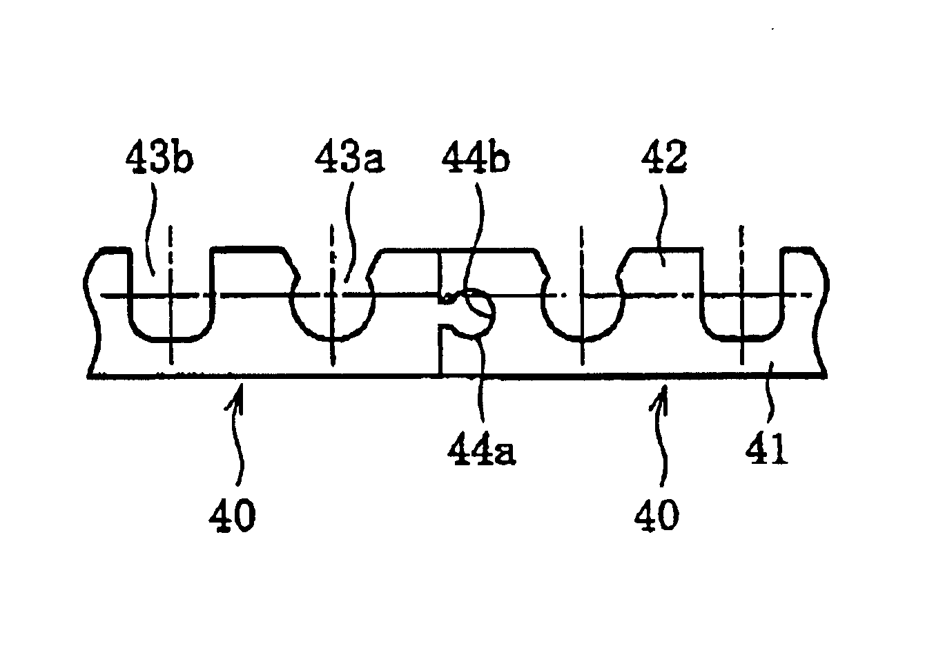
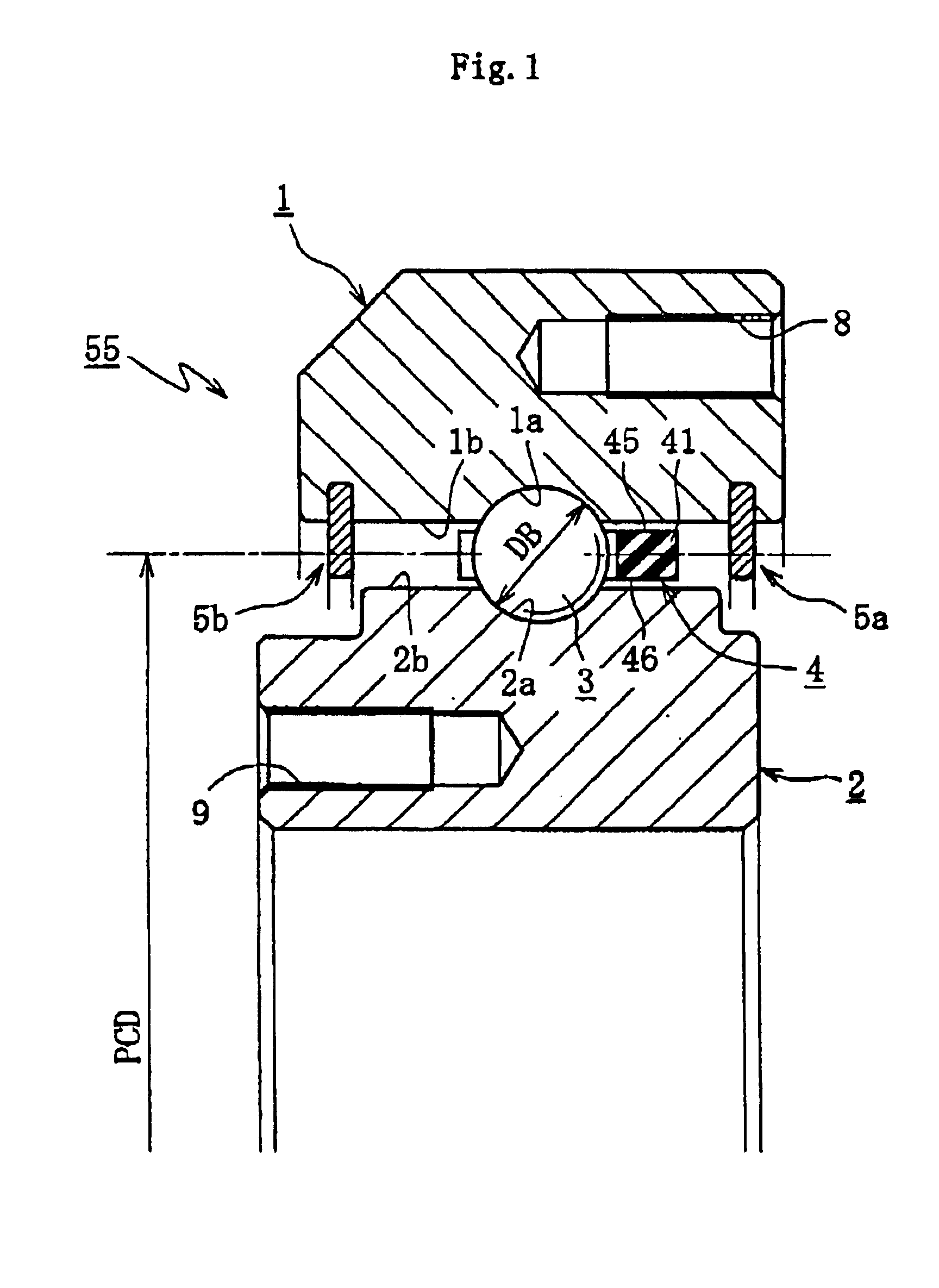
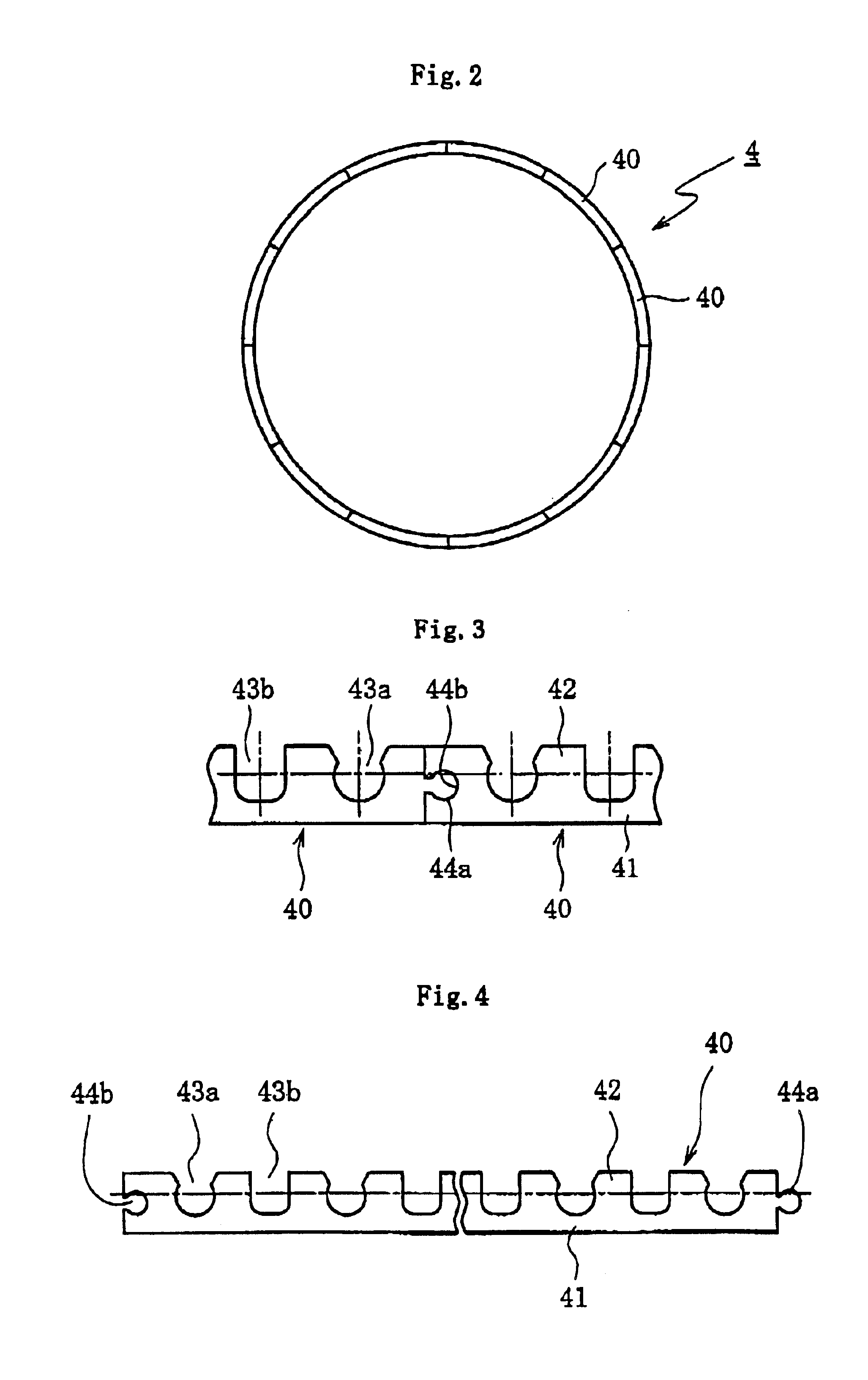
FIG. 1 shows the cross-sectional construction of a ultrathin-walled rolling bearing 55 used in CT scanner devices. This bearing 55 comprises an annular outer ring 1, an annular inner ring 2 disposed concentrically on the inner peripheral side of the outer ring 1, and rolling elements, or balls 3 in this case, rollably interposed between the raceway surface 1a of the outer ring 1 and the raceway surface 2a of the inner ring 2, a cage 4 for holding the balls 3 at circumferentially equispaced intervals, and seals 5a and 5b for sealing the openings at the opposite ends of the bearing.

In the drawings, balls are illustrated as the rolling elements 3, but rollers maybe used. And, a single row rolling bearing having a single row of rolling elements 3 is shown, but the invention is not limited thereto, and a double row rolling bearing having two rows of rolling elements may be used.

This bearing is an ultrathin-walled rolling bearing in which the pitch circle diameter PCD is about 500 mm-1500...


PUM


Abstract

The designing of an annular integral type is established by forming a cage of a resin material that satisfies the condition (a) that the ratio of its linear expansion coefficient to that of bearing steel is not more than 2 or the condition (b) that its water absorption percentage is not more than 0.5%, or both conditions (a) and (b), thereby preventing the occurrence of abnormal sounds by stabilizing the behavior of a segment type cage for an ultrathin-walled rolling bearing.

Description

BACKGROUND OF THE INVENTION1. Field of the InventionThe present invention relates to an ultrathin-walled rolling bearing used in industrial robots, machine tools, medical instruments, and the like, and more particularly it relates to an arrangement for stabilizing the behavior of a segment type cage of resin incorporated into an ultrathin-walled rolling bearing, so as to reduce the rubbing sound that is produced when the cage comes in contact with the bearing rings.2. Description of the Prior ArtIn FIG. 8, an example of a CT scanner device that is a kind of medical instrument is shown. In the CT scanner device, X-rays produced by an X-ray tube device 50 are applied to a subject 53 through a wedge filter 51 for uniformizing their intensity distribution and a slit 52 for restricting the intensity distribution. The X-rays passing through the subject 53 are received by a detector 54, where they are converted into an electric signal, which is then fed to an unillustrated computer. Such p...

Claims


Application Information

Patent Timeline
IPC IPC(8): F16C33/38F16C33/41F16C19/02F16C19/16F16C33/44F16C19/06
CPCF16C19/163F16C33/3812F16C33/416F16C33/418F16C33/44F16C2316/10F16C2300/14
Inventor HIRAMATSU, KENGO
Owner NTN CORP
Why Eureka
Try Eureka