Raceway for providing power and communications connectivity

a technology of power and communication lines, applied in the direction of insulated conductors, flat/ribbon cables, cables, etc., can solve the problems of high price, limited flexibility, and limited solution, and achieve the effect of reducing the likelihood of someone being injured

Inactive Publication Date: 2005-01-18
STRONG PROD GRP LTD
View PDF12 Cites 9 Cited by
  • Summary
  • Abstract
  • Description
  • Claims
  • Application Information

AI Technical Summary

Benefits of technology

In an advantageous embodiment, that is described in detail hereinafter, the one or more sloping sides of the present invention provide a gradual transition from the height of the floor (which may be thought of as having a height of logical zero) to a relative top of the raceway, preferably at its highest point (possibly at the apex of the fastener, which as stated above integrates the raceway and the floor cover). Once installed, this raceway substantially reduces a likelihood that someone or something will trip over the raceway. It is important to note therefore that the height of the raceway (the height of th

Problems solved by technology

This solution is limited for practical reasons to those users whose furniture is close to a wall or column having an appropriate outlet.
Flexibility is of course limited by the heed for a “tether” of lines from a desk to the outlet.
A drawback to this approach is high price, which is associated with a need for either ramps or steps to walk on the floor or a depressed floor slab (which is only an option if a structure is so designed initially) to accommodate a height of the raised floor.
Common problems of this app

Method used


Image

  • Raceway for providing power and communications connectivity
  • Raceway for providing power and communications connectivity
  • Raceway for providing power and communications connectivity

Examples


Embodiment Construction

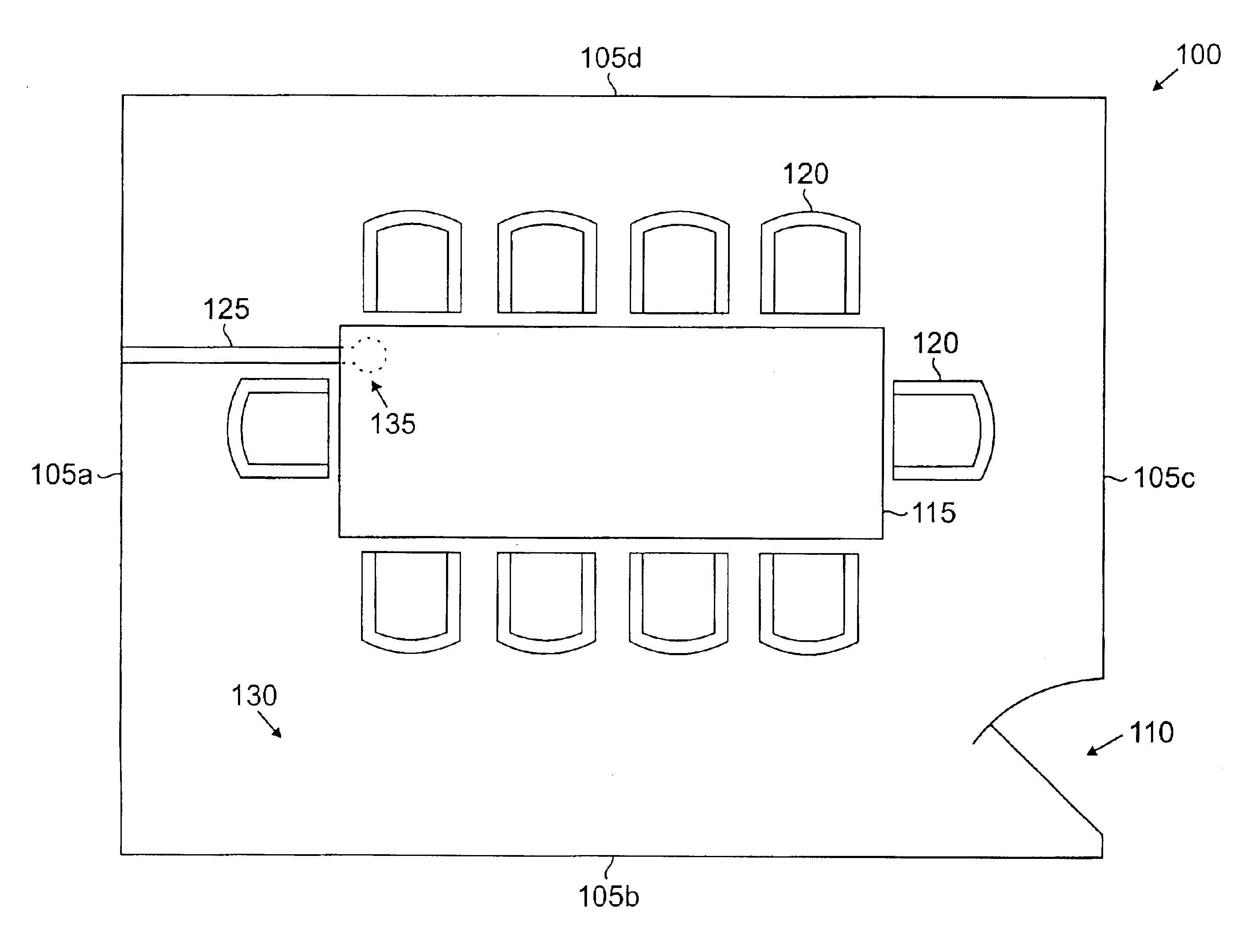
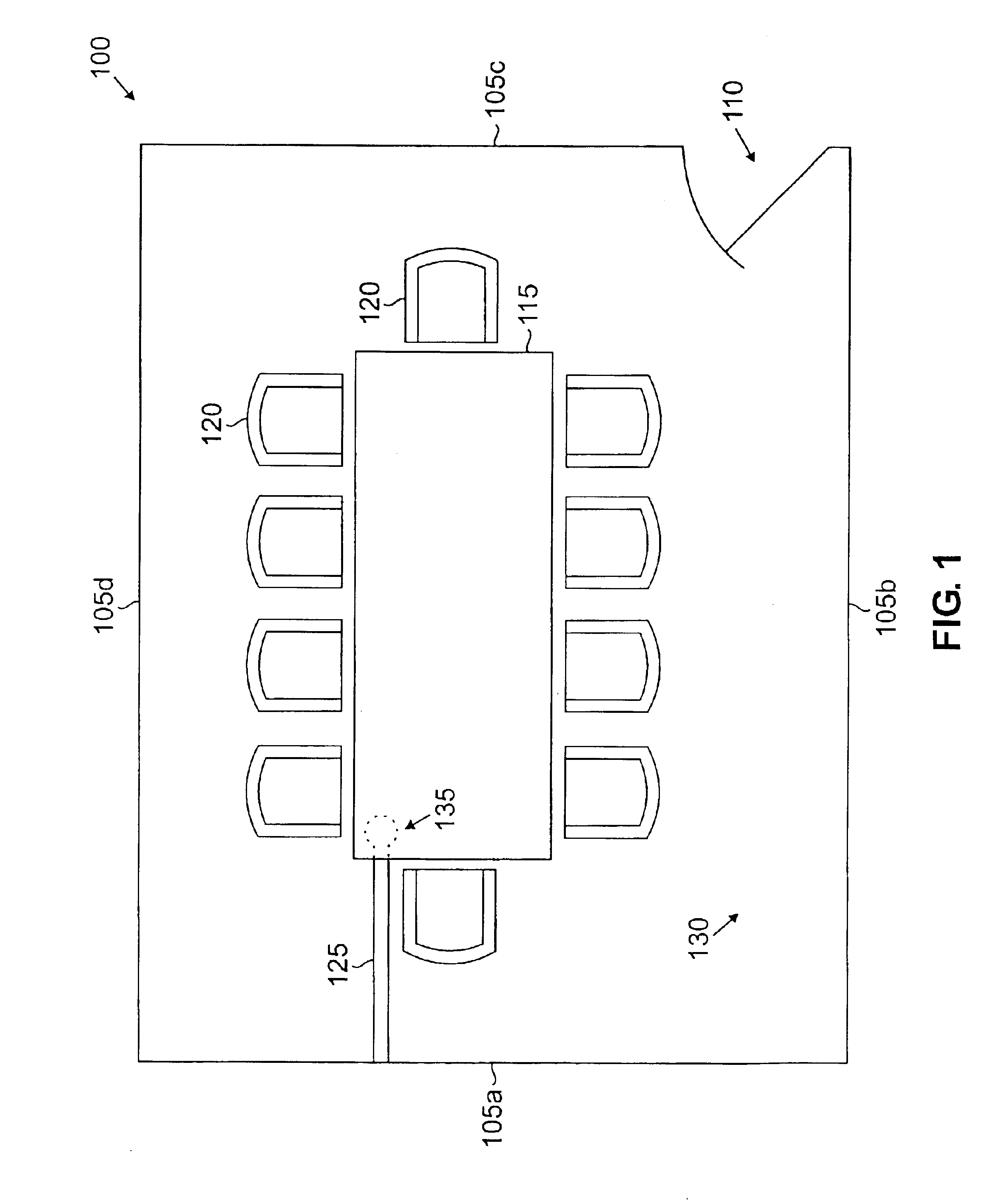
Referring initially to FIG. 1, illustrated is a top view block diagram of an exemplary structure (generally designated 100), such as a room in a building, having four supports (four walls) 105 therefor, that illustratively includes a doorway 110, a conference table 115, a plurality of chairs 120, a raceway 125 and a floor 130—raceway 125 providing power or communications connectivity according to the principles of the present invention. Because exemplary raceway 125 is associable with any suitable structure 100, support 105, floor 130 or the like, FIG. 1 is illustrative only.

Exemplary raceway 125 may be permanently or impermanently associated with exemplary floor 130 of structure 100 to provide a connectivity between a location 135 on floor 130 and support 105a. Differentiation between permanent and impermanent may, in one context, be thought of as an association of raceway 125 with structure 105a or floor 130 wherein it (1) may not be disassociated therefrom or used again (i.e., pe...


PUM


Abstract

The present invention introduces a raceway for association with a floor and a support of a structure to provide power or communications connectivity between the support and a location on the floor. The raceway includes a housing and a fastener. The housing, that is substantially equal in length to a distance between the location on the floor and the support, includes a conduit and a sloping side. The conduit is adapted to receive one or more lines from the support, the one or more lines are capable of communicating signals to the location on the floor. The sloping side, that has a length substantially equal to a length of the raceway, provides a gradual transition between the floor and the raceway and is capable of being substantially covered by a floor cover. The fastener can be associated with the housing to at least substantially ensconce the one or more lines. The fastener and the housing are capable of cooperating to integrate the raceway and the floor cover.

Description

TECHNICAL FIELD OF THE INVENTIONThe present invention is directed generally to raceways having power and communications lines and, more specifically, to a raceway that is associable with a floor and a support (e.g., a wall, a column, etc.) of a structure (e.g., a room, a building, etc.) and is capable to reticulate power or communication lines proximate to a location within the structure.BACKGROUND OF THE INVENTIONThe need for connectivity, that is the ability to “plug in” to a technology available in a work place, or, now, in a home (collectively, “work space”), has never been greater. In each setting, telecommunications, television, computer, power or like systems are the norm, causing every work space to have a physical connection to power and communications lines. This may be seen in offices, office system cubicles, as well as in libraries, classrooms, training rooms, conference rooms, team work rooms and, even, corporate lobbies and lounges.Conventional means to achieve this co...

Claims


Application Information

Patent Timeline
IPC IPC(8): H02G3/04E04C2/52H02G9/04
CPCH02G3/283
Inventor STRONG, CLINTON R.
Owner STRONG PROD GRP LTD
Why Eureka
Try Eureka