Communications cable and method for making same

a technology of communication cables and cables, applied in the field of data communications cables, can solve the problems of twisted pairs, affecting impedance, and flexing or bending, and achieve the effect of high, accurate impedance levels

Inactive Publication Date: 2005-01-18
BAILEY MAURICE
View PDF40 Cites 46 Cited by
  • Summary
  • Abstract
  • Description
  • Claims
  • Application Information

AI Technical Summary

Benefits of technology

These objects are achieved in improved data cable compliant with the USB 2.0 specifications, which has a flat configuration and does not utilize twisted pairs of wires as conductors. The new USB cable is provided with a pair of multifilament, single wire conductors encased within an inner jacket having high dielectric strength. The wires may be formed of various copper and cadmium alloys. They are co-extruded simultaneously with the inner jacket and are held in parallel spaced relationship at a specified distance from each other and at a specified distance from the outside surface of the inner jacket. In this manner, accurate impedance levels can be achieved.

Problems solved by technology

There are some basic problems or drawbacks with each of these prior art cables.
The first is that there is some manufacturing problems associated with control over impedance characteristics.
The second problem is controlling matched lengths of wires when they are being twisted, and the third is that twisted pairs, when flexed or bent, have a tendency to separate from each other.
All of these issues affect impedance.
Next, are the costs and time required in the manufacturing process for the additional step of fabricating the twisted pairs of conductor wires prior to fabrication of the cable.
While the data transmission characteristics and transmission rates for cables manufactured to these specifications can, and are routinely met, round, sectional shaped cables have certain inherent limitations regarding their use.
The primary limitation of the round cable is the fact that it is not amendable to being wound around a spool in a tight, compact configuration.
However, the problem with the cable disclosed in the King patent is that it still has the manufacturing drawbacks of the twisted pair configuration for the conductor wires.

Method used


Image

  • Communications cable and method for making same
  • Communications cable and method for making same
  • Communications cable and method for making same

Examples


first embodiment

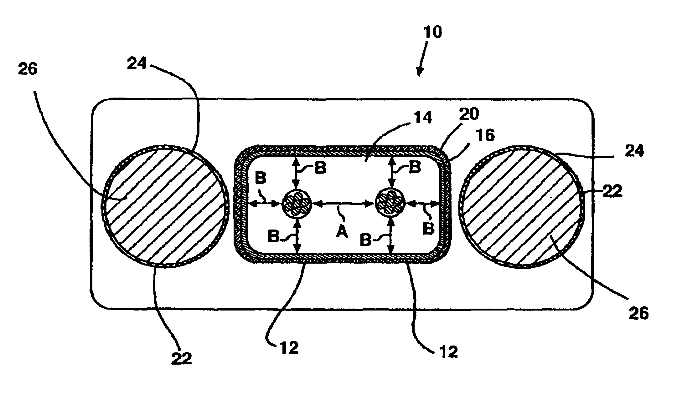
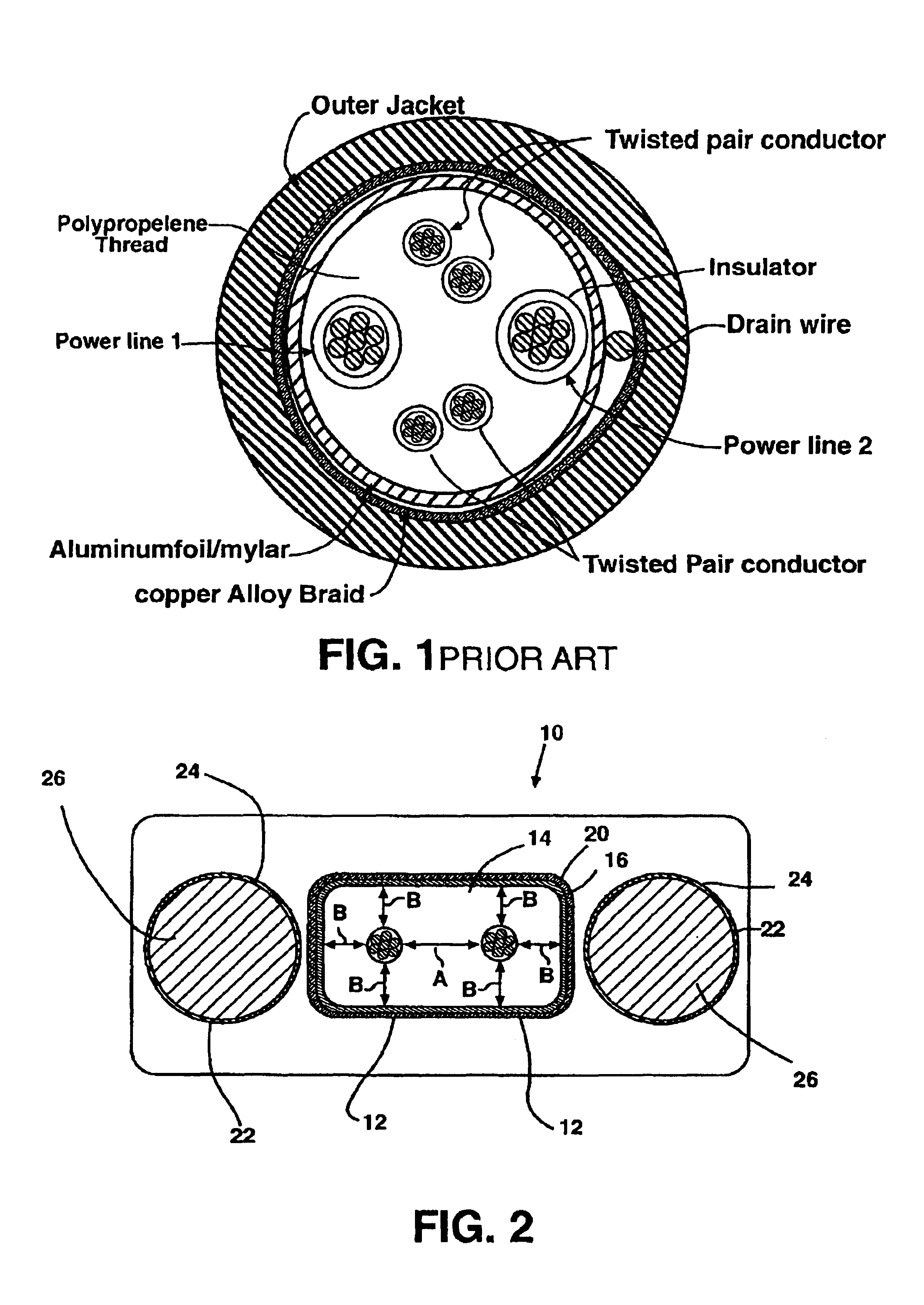
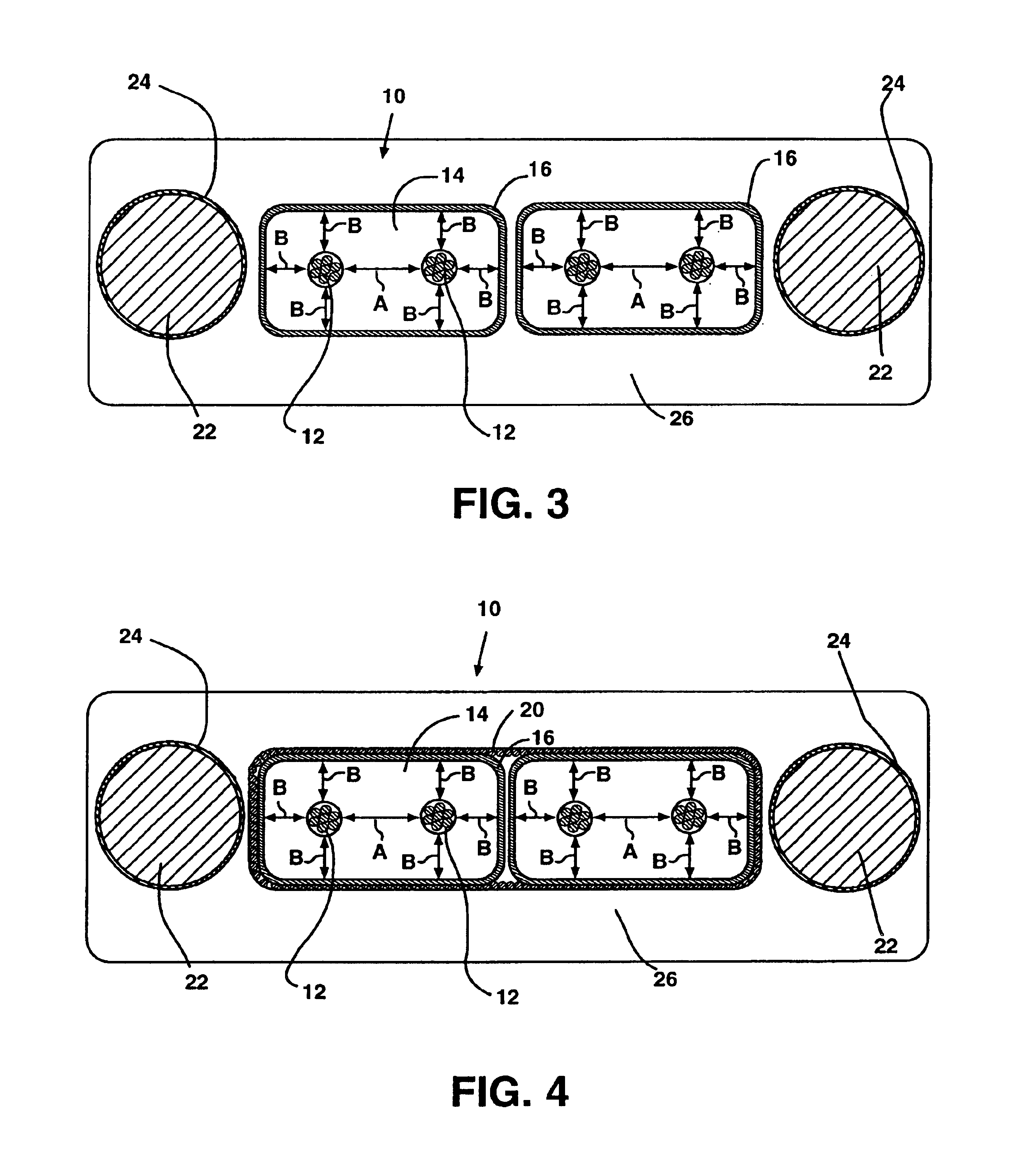
Referring to FIG. 3, there is shown a new flat cable in a typical IEEE 1394 configuration. In this configuration, the cable includes a pair of inner jackets 14 encasing conductors 12 in much the same manner and utilizing the same materials and general dimensions as those disclosed and shown for the USB cable of FIG. 2. Like the USB cable of FIG. 2, power leads 22 are encased within jackets 24 are also provided. All of this is encased within an outer jacket 26 formed of essentially the same materials as that described in the embodiment shown in FIG. 2. This embodiment shows only one shield 16 provided around the inner jacket 14.

In addition to what is described above, in the embodiment shown in FIG. 3, drain wires 18 are also provided for reduction and removal of any induced currents. The drain wires run along the longitudinal direction of the shielded conductors on the outside or the inside of the conductive shields. The drain can conduct through the shielding to eliminate radio freq...

second embodiment

Now referring to FIG. 4, there is shown a cable conforming to IEEE 1394 specifications. This cable provides for the pairs of conductors 12 encased within inner jackets 14 to be positioned adjacent to each other. In this case, each inner jacket 14 is wrapped within a first shield 16 as described above for the USB disclosed above and shown in FIG. 2. Shields 16 are positioned in contact with each other during the extrusion process for the outer jacket 26. Also provided is drain conductor 18, which runs longitudinally between and adjacent to both inner shields 16 and in a conductive relationship with both of them. All of this is then encased within an outer shield 28. This assembly is then extruded into outer jacket 26 along with a pair of power leads 22. Again, the selection of materials for each of the various component parts of the cable is essentially the same as that described in the embodiment shown in FIG. 2, and likewise, certain features of cables may be omitted depending on t...


PUM

PropertyMeasurementUnit
diameteraaaaaaaaaa
distanceaaaaaaaaaa
thickaaaaaaaaaa

Abstract

A flat communication cable is provided having one or more pairs of data conductor wires, which are single wires as opposed to twisted pairs, with each pair of conductors co-extruded and encased within an inner jacket. Shielding is provided around the inner jackets and encased within an outer jacket together with appropriate power leads and drain lines.

Description

BACKGROUND OF THE INVENTION1. Field of the InventionThe present invention generally relates to data communications cables, and more particularly relates to electrical communications / data cabling, which is formed of single, multi-strand wire conductors, as opposed to twisted pair conductors, in a flat, as opposed to round, configuration.2. Background InformationIn Universal Serial Bus (USB) specification cables, the properties of the cable must be adapted to carry information in accordance with the outlined specifications for the particular cable, as well as to comply with the adapter plugs that accompany USB outlets. These specifications include, amongst others, desired or required transmission rates or bandwidths, voltage ratings, temperature ratings, insulation resistance, conductor resistance or impedance at specified temperatures. In some USB cables, shielding is provided and the conductors are generally configured of four wires, arranged in two insulated, twisted pairs of data ...

Claims


Application Information

Patent Timeline
Patent Type & Authority Patents(United States)
IPC IPC(8): H01B11/10H01B11/00H01B11/02H01B9/00H01B7/08
CPCH01B7/0823H01B7/0861H01B11/1091H01B11/002H01B9/003
Inventor WILLIAMS, ROGER D.YOUNG, DARREN V.
Owner BAILEY MAURICE
Why Eureka
Try Eureka