
Wien filter and electron microscope using same

a filter and electron microscope technology, applied in the direction of instruments, mass spectrometers, beam deviation/focusing by electric/magnetic means, etc., can solve the problems of inability to place a number of power supplies in locations at high electric potential, inability to put tang's filter into practical use, and inability to achieve secondary aberration. , to achieve the effect of less secondary aberration

Inactive Publication Date: 2005-01-18
JEOL LTD
View PDF1 Cites 11 Cited by
  • Summary
  • Abstract
  • Description
  • Claims
  • Application Information

AI Technical Summary

Benefits of technology

The present invention provides a Wien filter with less secondary aberration than conventional filters. The filter has 12 poles with front ends facing the optical axis having a 12-fold rotational symmetry about the optical axis in the XY-plane perpendicular to the optical axis. The filter also produces at least a dipole electric field in the X-axis direction and a dipole magnetic field in the Y-axis direction. The electron microscope designed with this filter causes an electron beam to hit a sample via the filter, which passes only electrons having a certain energy.

Problems solved by technology

However, when the Tang's filter is put into practical use, a drawback occurs.
It is not practical to place a number of power supplies in locations at high electric potentials.
For these reasons, the Tang's filter has not been put into practical use.
However, it has still been difficult to reduce the aberration down to zero.
Generally, a Wien filter has a considerably large amount of second-order aberration.
However, the component stays at large values in the fringing fields and cannot be reduced to a small value.
Therefore, the conventional Wien filter has the problem that the second-order aberration cannot be reduced.

Method used


Image

  • Wien filter and electron microscope using same
  • Wien filter and electron microscope using same
  • Wien filter and electron microscope using same

Examples


Embodiment Construction

Wien filters according to embodiments of the present invention are hereinafter described by referring to FIGS. 1-5.

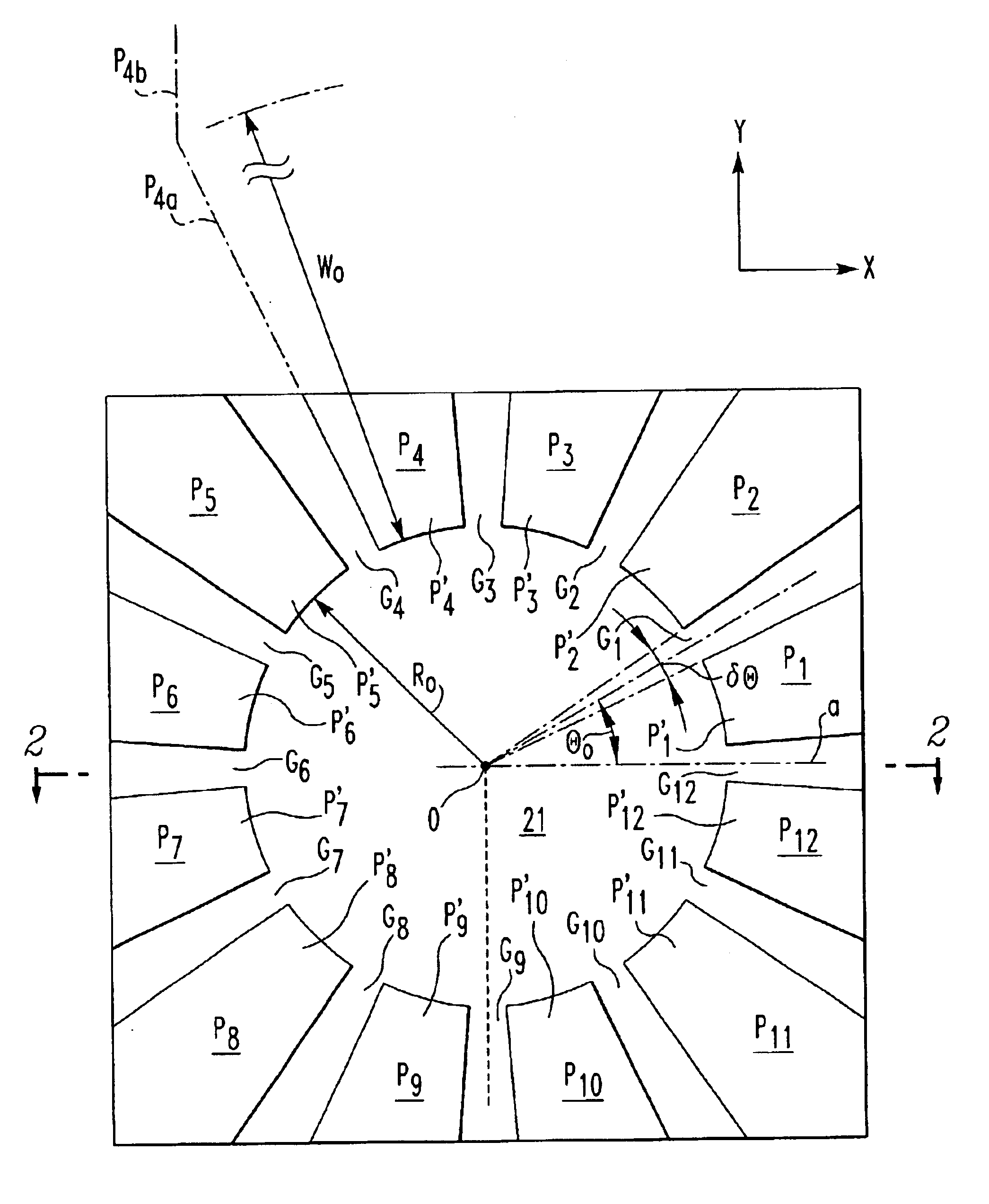
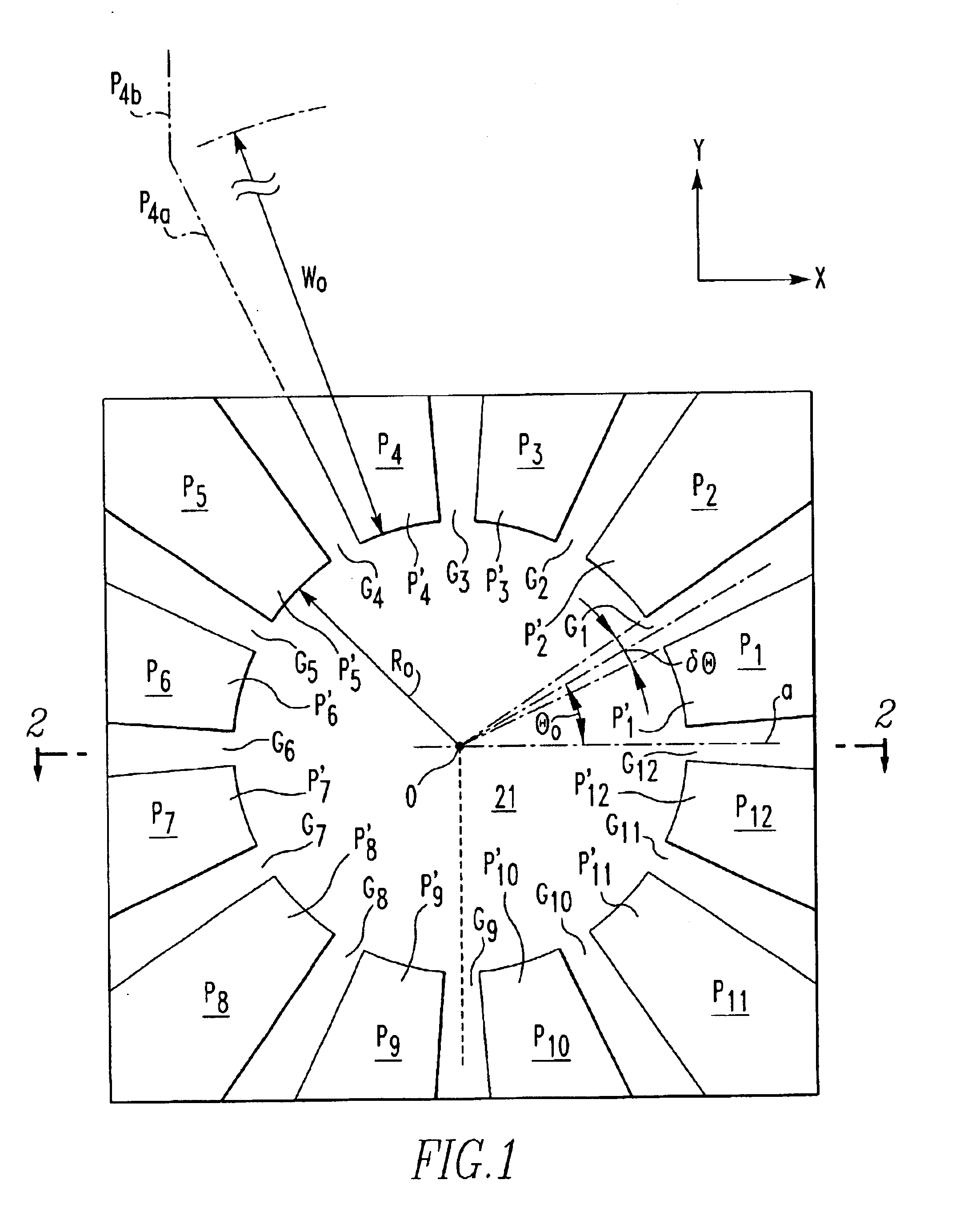
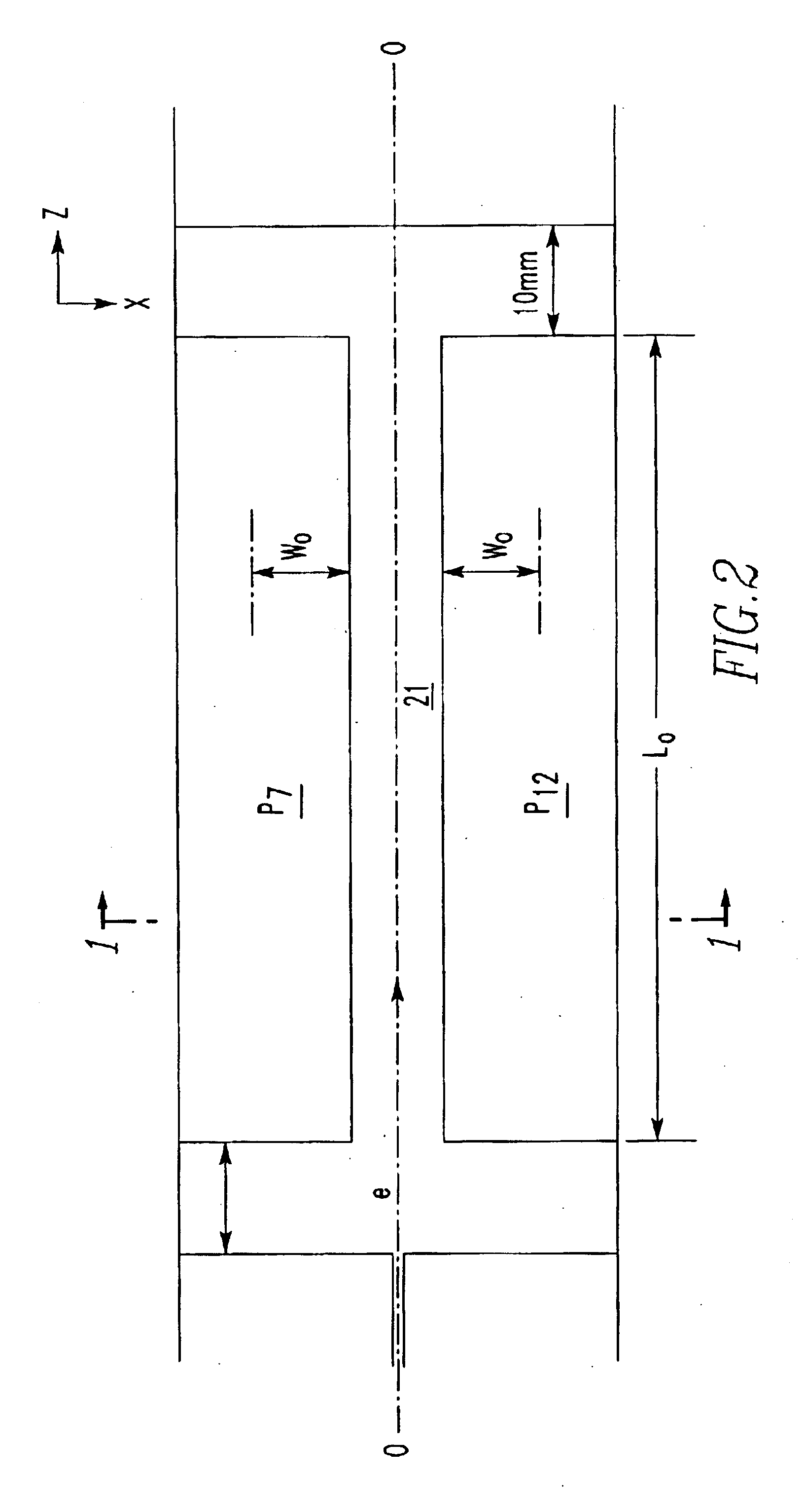
Referring to FIGS. 1-4, there is shown a Wien filter according to one embodiment of the present invention. Generally, this filter has an optical axis O parallel to the Z-axis direction, and produces at least a dipole electric field E1 in the X-axis direction and a dipole magnetic field B1 in the Y-axis direction. The filter is fitted with 12 poles P1 to P12 extending substantially parallel to the optical axis O. The front ends P1′ to P12′ of the poles P1 to P12 which face the optical axis O have a 12-fold rotational symmetry about the optical axis O within the XY-plane. The X-, Y-, and Z-axes are mutually orthogonal Cartesian axes. The 12 poles P1 to P12 are made of a magnetic material such as iron, nickel, or Permalloy. The Wien filter is described in further detail below.

As shown in FIGS. 1 and 2, the Wien filter according to this embodiment has the 12 poles P1 to P12...


PUM


Abstract

A Wien filter is provided in which a less amount of secondary aberration is produced than conventional. This filter has 12 poles. These poles have front ends facing the optical axis. These front ends have a 12-fold rotational symmetry about the optical axis within the XY-plane perpendicular to the optical axis.

Description

BACKGROUND OF THE INVENTION1. Field of the InventionThe present invention relates to a Wien filter (E×B filter) used in an energy filter for use in an electron microscope, mass filter, spin rotator, monochrometer, energy analyzer, or the like. The present invention also relates to an electron microscope using such a Wien filter.2. Description of Related ArtAccelerated charged particles, such as electrons, are deflected toward positive poles with respect to an electric field. With respect to a magnetic field, the particles are deflected perpendicular to the direction of travel of the particles and to the magnetic field. A Wien filter makes use of these phenomena and uses electric and magnetic fields that are placed perpendicular to each other within a plane perpendicular to the direction of travel of the charged-particle beam. The beam is made to move straight in a certain direction.The condition under which a charged-particle beam goes straight through a Wien filter is known as the ...

Claims


Application Information

Patent Timeline
Patent Type & Authority Patents(United States)
IPC IPC(8): H01J37/26H01J37/05
CPCH01J37/261H01J2237/262H01J2237/057
Inventor LOPEZ, G. MARTINEZTSUNO, KATSUSHIGE
Owner JEOL LTD
Learn More