Interferometric antenna array for wireless devices

a wireless device and interferometer technology, applied in the direction of different interaction antenna combinations, climate sustainability, sustainable buildings, etc., can solve the problems of electromagnetic wave propagation near the user's antenna array and head, unfavorable operation of directional configurations in the industry, and inconvenient use of directional configurations, so as to prevent undesirable energy from negatively affecting operation

Inactive Publication Date: 2005-01-18
MYERS STEVEN LLOYD MR
View PDF28 Cites 41 Cited by
  • Summary
  • Abstract
  • Description
  • Claims
  • Application Information

AI Technical Summary

Benefits of technology

The present invention provides an interferometric antenna array as a simple, unique, natural and absolute means for controlling energy around a desired location such as a user's head or body or as a means toward preventing undesirable energy from negatively affectin

Problems solved by technology

Often these types of antennas result in an asymmetric radiation pattern because the shape and dimensions of the ground plane of a printed wire board (PWB) (incorporating the phone's circuitry) that is used as a counterpoise for the antenna element results in an unequal current distribution in th

Method used


Image

  • Interferometric antenna array for wireless devices
  • Interferometric antenna array for wireless devices
  • Interferometric antenna array for wireless devices

Examples


Embodiment Construction

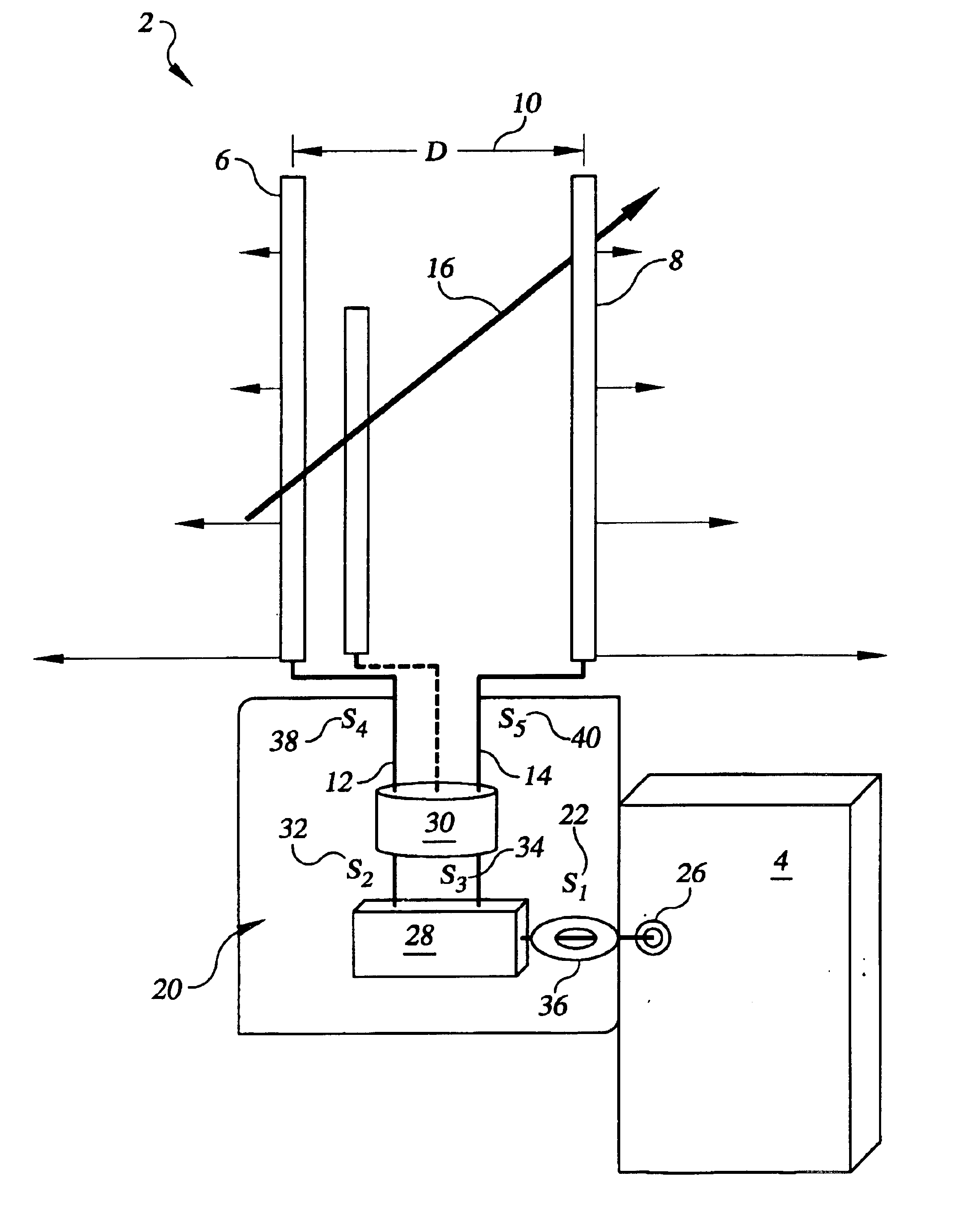
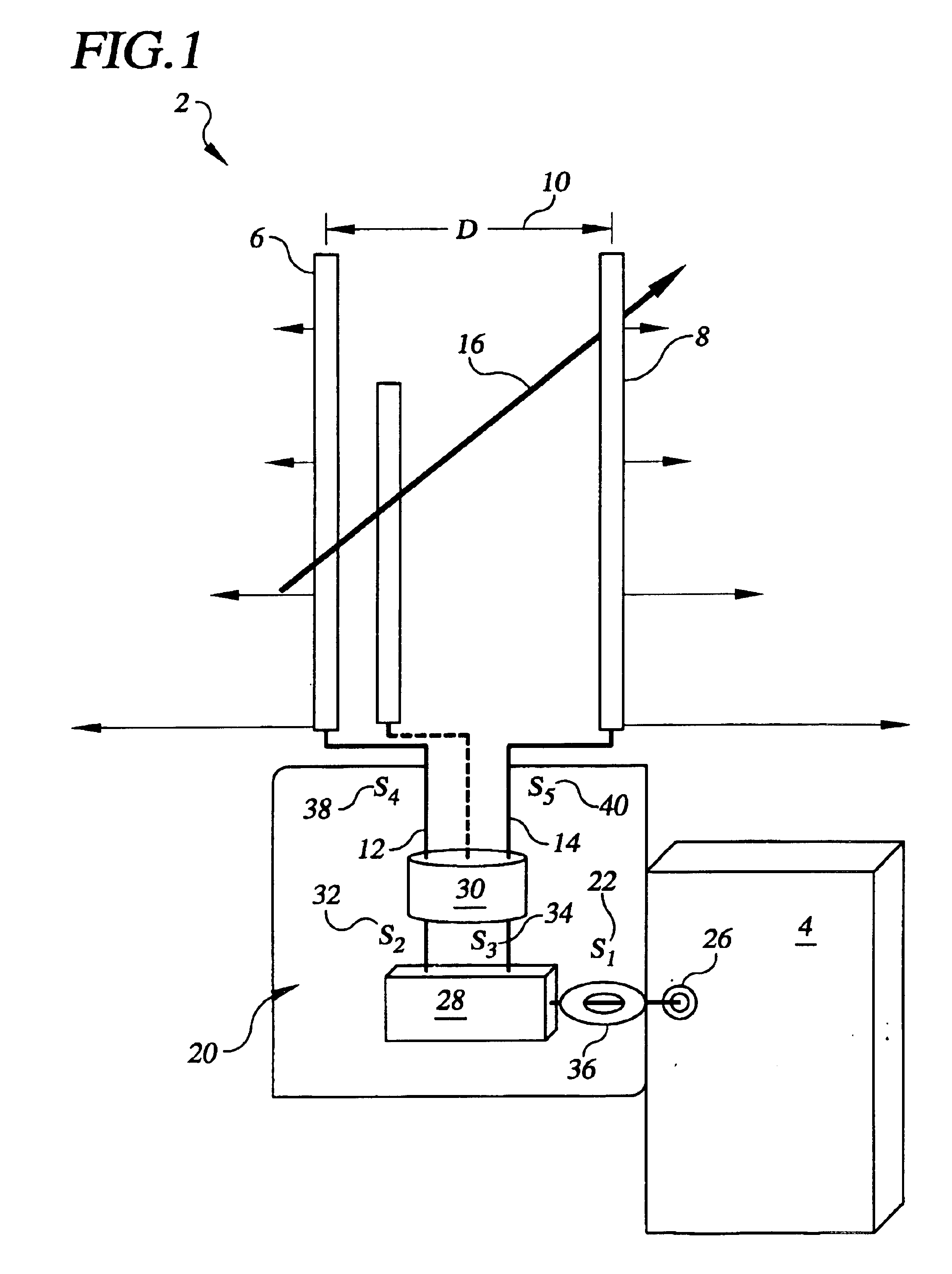
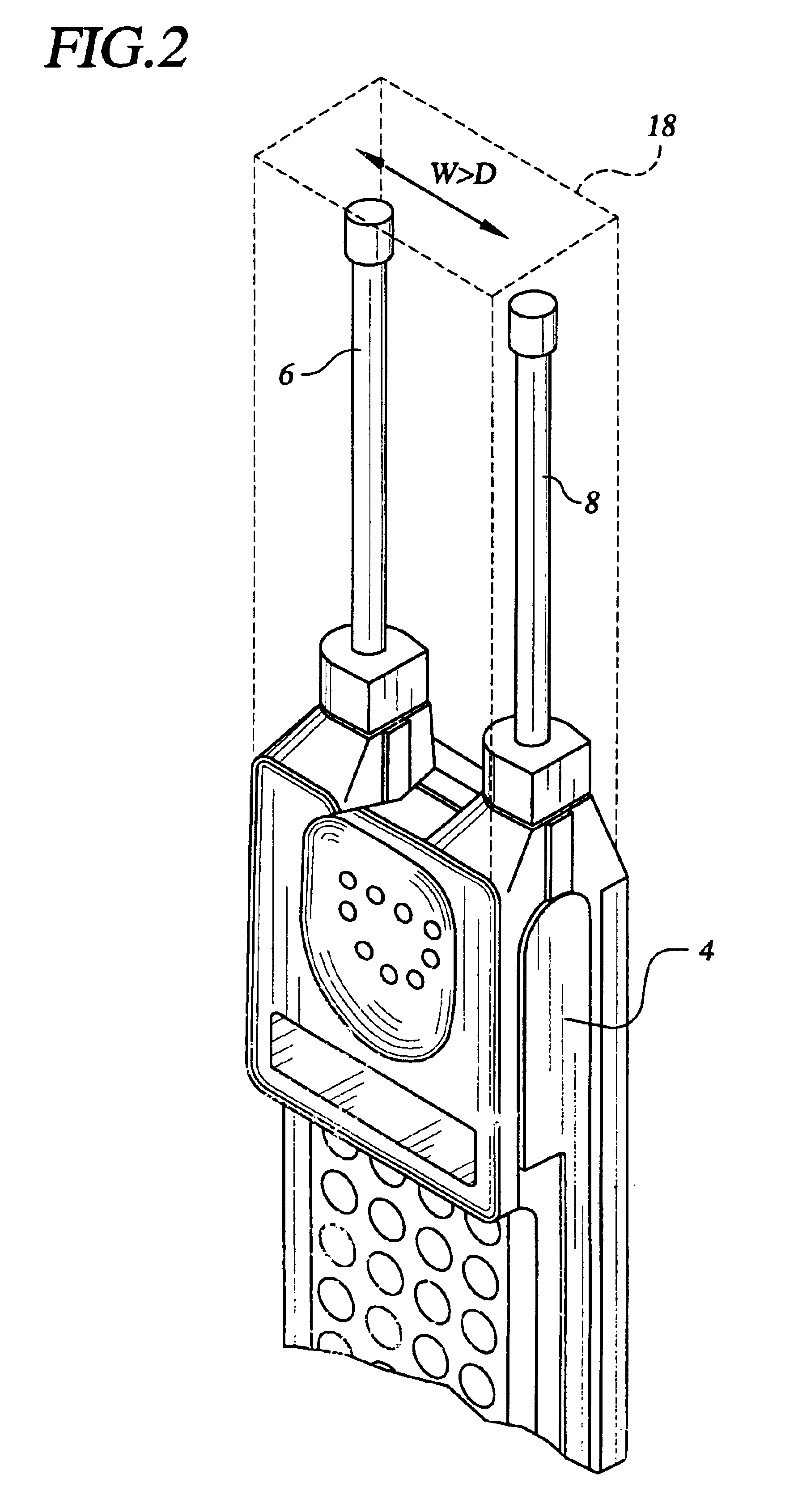
Referring now to the accompanying drawing, wherein like numerals depict like parts throughout, embodiments of the present invention are illustrated in FIGS. 1-7. Although certain preferred embodiments are depicted in the context of cellular phones, the use of an interferometric antenna array in accordance with the present invention in reducing or eliminating unwanted radiation will be readily appreciated by an artisan to be applicable to wireless communications devices operating in multiple frequency ranges, such as cellular telephones (824-890 MHz and 860-980 MHz), PCS devices (1710-1880 MHz, 1750-1870 MHz, and 1850-1990 MHz), cordless telephones (902-928 MHz), military and Satcom communications (225-400 MHz), or BLUETOOTH™ devices (2.4-2.5 GHz), and complying with protocols such as 802.11, CDMA and CDPD.

In one embodiment illustrated in FIG. 1, the present invention provides a two element antenna array 2 adapted for use in a wireless communications device 4. The array 2 is designed...


PUM


Abstract

An interferometric antenna array for use with a wireless communications device in reducing electromagnetic energy in a region proximate to the antenna array. The antenna array comprises two or more radiating elements coupled through circuitry to the wireless communications device. The circuitry operates to appropriately divide a signal from the communications device into a plurality of signals and to phase-shift the plurality of signals such that the electromagnetic wave pattern formed proximate to the antenna array by the two or more radiating elements, which are fed by the phase-shifted plurality od signals, includes a spatial null. The spatial null is located at a region where sensitive electronic equipment, or some portion of a user of the communications device is also located.

Description

FIELD OF THE INVENTIONThe present invention relates generally to an apparatus and method for controlling electromagnetic wave propagation from wireless communications devices for reducing the amount of undesired energy to a user's head or body, or to sensitive electronics that might be proximate to the radiating antennas. More specifically, the present invention uses an interferometric array of two or more antennas to nullify any undesired radiation at selected areas proximate to the interferometric array, which additionally results in far field nulls.BACKGROUND OF THE INVENTIONPortable wireless communications devices have received scrutiny regarding their safety with respect to the potential danger associated with the transmission of the signals from such apparatus. When a user of a wireless communication device, such as a cellular telephone, talks on the device, he holds the telephone up his head so that the earpiece is in contact with his ear. In close proximity is the antenna, w...

Claims


Application Information

Patent Timeline
IPC IPC(8): H01Q1/24H01Q21/29H01Q21/00H01Q3/24
CPCH01Q1/245H01Q21/29H01Q3/24Y02B60/50
Inventor JOHNSON, JAMES R.MYERS, STEVEN L.
Owner MYERS STEVEN LLOYD MR
Why Eureka
Try Eureka