Dental image processing method and system

a processing method and dental image technology, applied in the field of dental surgery, can solve the problems of adding a further inaccuracy to an analysis of this kind, adding up, and difficulty in an analysis, and achieve the effect of powerful tools for designing

Inactive Publication Date: 2005-01-18
ALIGN TECH
View PDF11 Cites 256 Cited by
  • Summary
  • Abstract
  • Description
  • Claims
  • Application Information

AI Technical Summary

Benefits of technology

In accordance with the invention a novel method and system is provided in which information and data available from one type of teeth imaging technique is transferred and used in an image obtained by another kind of teeth imaging technique. This transfer of information provides the dentist or the orthodont with a powerful tool for designing of orthodontic treatment.
In accordance with another embodiment of the invention, the method and system are used for proper design of a dental implant or of a crown. For proper placement of an implant, the bone has to be carefully studied beforehand and examined whether it can receive the dental implant In addition, the exact position and orientation of the dental implant has to be properly pre-designed. Typically, for a proper design of an implant, a three-dimensional virtual image of a teeth model is brought into registration with both a lateral cephalometric image and at times also with a frontal cephalometric image. This will allow to properly predict the manner of receipt of the implant within the bones of the jaw.
One particular example of analysis which can be made by such simulation is to determine the effect of such displacement on soft facial tissue, particularly outer facial tissue. This will allow an estimation of the effect of the orthodontic treatment on the esthetic appearance of the individual.

Problems solved by technology

It is thus difficult in an analysis performed on such an image to distinguish between bilateral structures to trace them independently.
Additionally, facial aspects are not entirely asymmetrical, this may add a further inaccuracy to an analysis of this kind.
Other sources of errors in a cephalometric image include different magnification of different aspects depending on the distance from the film and imperfect positioning of the patient in the cephalostat.
These all add up to considerable errors in cephalometry.

Method used


Image

  • Dental image processing method and system
  • Dental image processing method and system
  • Dental image processing method and system

Examples


Embodiment Construction

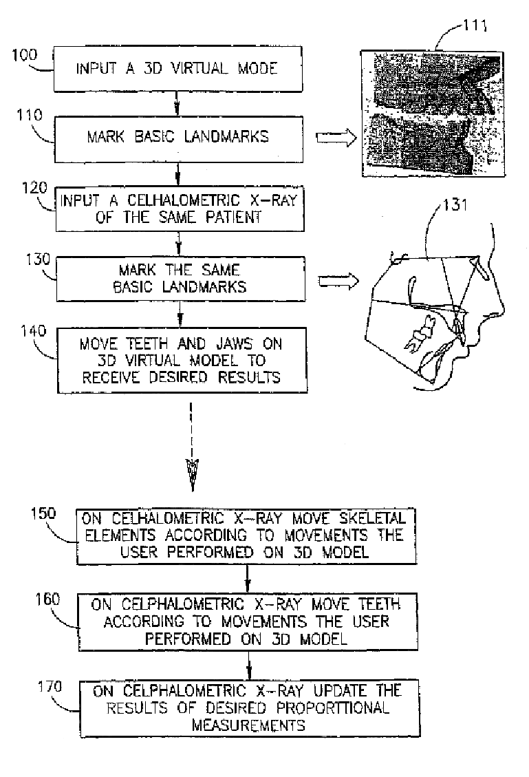
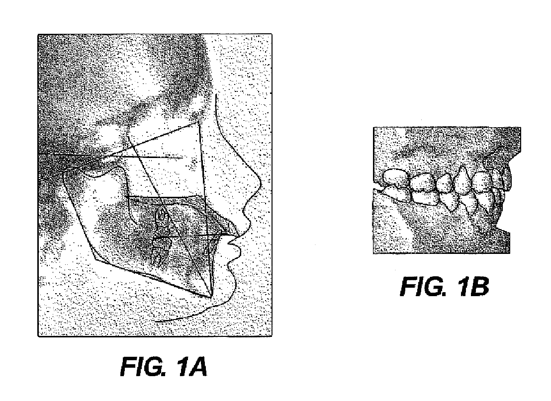
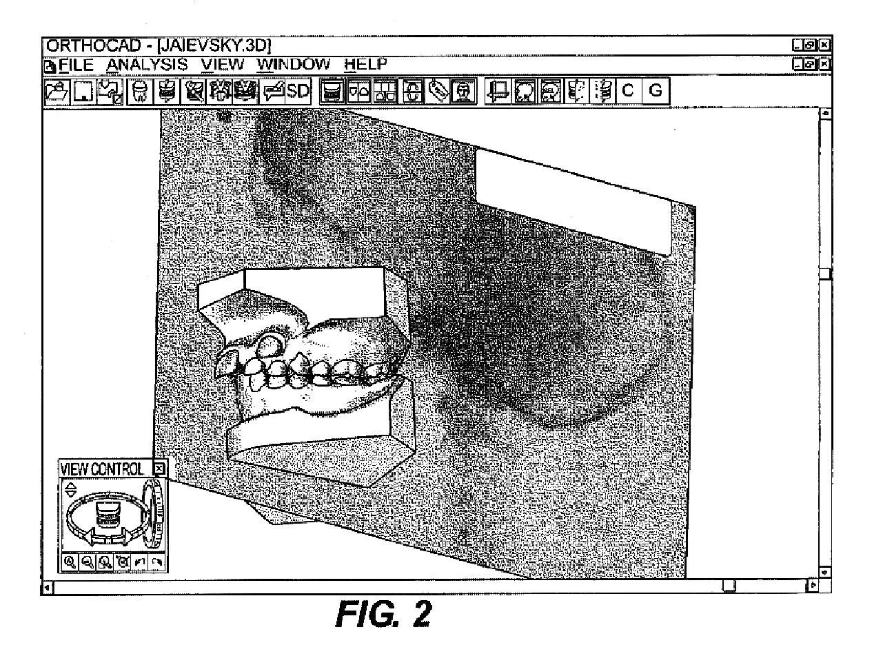
In accordance with the present invention images are acquired including at least one two-dimensional teeth image and at least one three-dimensional teeth image and both are combined for the purpose of improving the orthodont's ability to predict the effect of orthodontic treatment on various parameters. This combination allows the orthodont to considerably increase the depth of his understanding on the outcome of the orthodontic treatment. Hitherto, analysis which was made on a cephalometric images could not have been readily translated to the other tools available to him—this being the three-dimensional teeth model, typically a plaster model. In the reverse, information gained by him from studying a three-dimensional teeth model, could not have been readily translated to a cephalometric image. As is well known to the artisan, each one of the images allows a limited range of analysis which can be made and a true analysis can only be gained from thorough analysis based on the two type...


PUM


Abstract

An image processing method for use in dentistry or orthodontic is provided. Two images of teeth, one being a two-dimensional image and one a three-dimensional image are combined in a manner to allow the use of information obtained from one to the other. In order to combine the two images a set of basic landmarks is defined in one, identified in the other and then the two images are registered.

Description

FIELD OF THE INVENTIONThe present invention is generally in the field of dentistry and provides an image processing method and system useful as a tool by the dentist or orthodont.BACKGROUND OF THE INVENTIONThere are a wide variety of imaging techniques used routinely in orthrdontics. One important imaging technique is the so-called radiographic cephalometric technique. A radiographic cephalometric image is then used for a cephalometric analysis. Such an analysis is essentially a measurement system designed to describe relationships between the various parts of the skeletal, dental and soft tissue elements of the cranofacial complex. The two cephalometric images typically used are a lateral cephalometric image, which is of prime use in orthodontic and a front cephalometric image which is of somewhat less importance.Cephalometric methods enable to define certain norms of a skeletal, dental and soft tissue of the cranofacial complex. A cephalometric measurement of individuals can then ...

Claims


Application Information

Patent Timeline
Patent Type & Authority Patents(United States)
IPC IPC(8): A61B6/00A61B6/14A61B5/107G06T1/00G06T3/00
CPCA61B6/14A61C9/0046A61B6/501Y10S128/922
Inventor KOPELMAN, AVITAUB, ELDAD
Owner ALIGN TECH
Why Eureka
Try Eureka