
Materials moving blade

a technology of moving blades and materials, applied in soil-shifting machines/dredgers, snow cleaning, drilling equipment, etc., can solve the problems of affecting the disengagement of materials, damage and time delays of snow removal, and the connection or joint between the sides of the blades is not strong enough, so as to facilitate disengagement of materials, increase the strength and stability of the material mover, and facilitate disengagement.

Inactive Publication Date: 2005-01-25
DEGELMAN IND LP
View PDF2 Cites 41 Cited by
  • Summary
  • Abstract
  • Description
  • Claims
  • Application Information

AI Technical Summary

Benefits of technology

Yet another object of the present invention is to provide a gusset for strengthening a joint between substantially perpendicular members of a heavy equipment blade which easily sheds materials being plowed, for example, snow, ice and / or earth where the materials being moved or plowed contact only a contiguous forward facing surface to facilitate disengagement of the material from the blade or bucket.
A still further object of the present invention is to provide an easy to manufacture and economical support gusset to provide increased strength and stability of the material mover with the least amount of additional weight to the blade or bucket.

Problems solved by technology

A problem that arises with such apparatus is the lack of strength in the connection or joint between each sidewall attached at opposing ends of the blade.
Without any support other than the joint with the main blade, the thin sidewalls can be easily damaged, and are particularly susceptible to being bent outwards by sufficient snow loads within the confines of the box blade, especially as the machine pushes the blade with a load.
These previously known supports present several problems, including a space between the support and the joint in which objects could be caught up or entangled.
Also, such a horizontal support tends to form a shelf or trap for snow, ice or other debris which cannot become loosened without the operator intervening.
In snow plowing, snow may build up in and around these supports and in order to remove such build up of snow, the operator must strike the blade upon the ground surface to loosen the snow or must physically remove the buildup by exiting from the cab and scraping the snow out, all of which may cause damage and time delays with respect to snow removing.

Method used


Image

  • Materials moving blade
  • Materials moving blade
  • Materials moving blade

Examples


Embodiment Construction

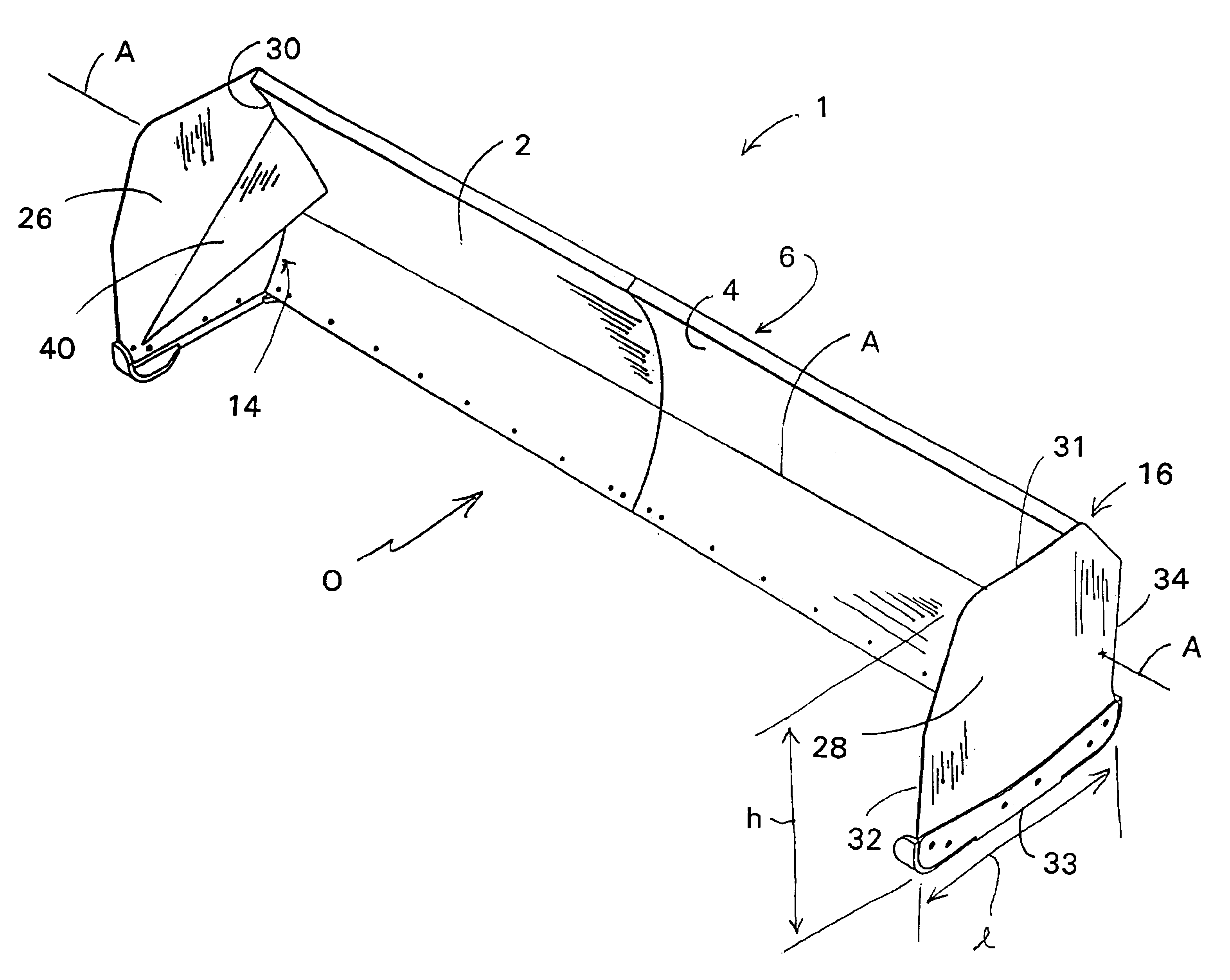
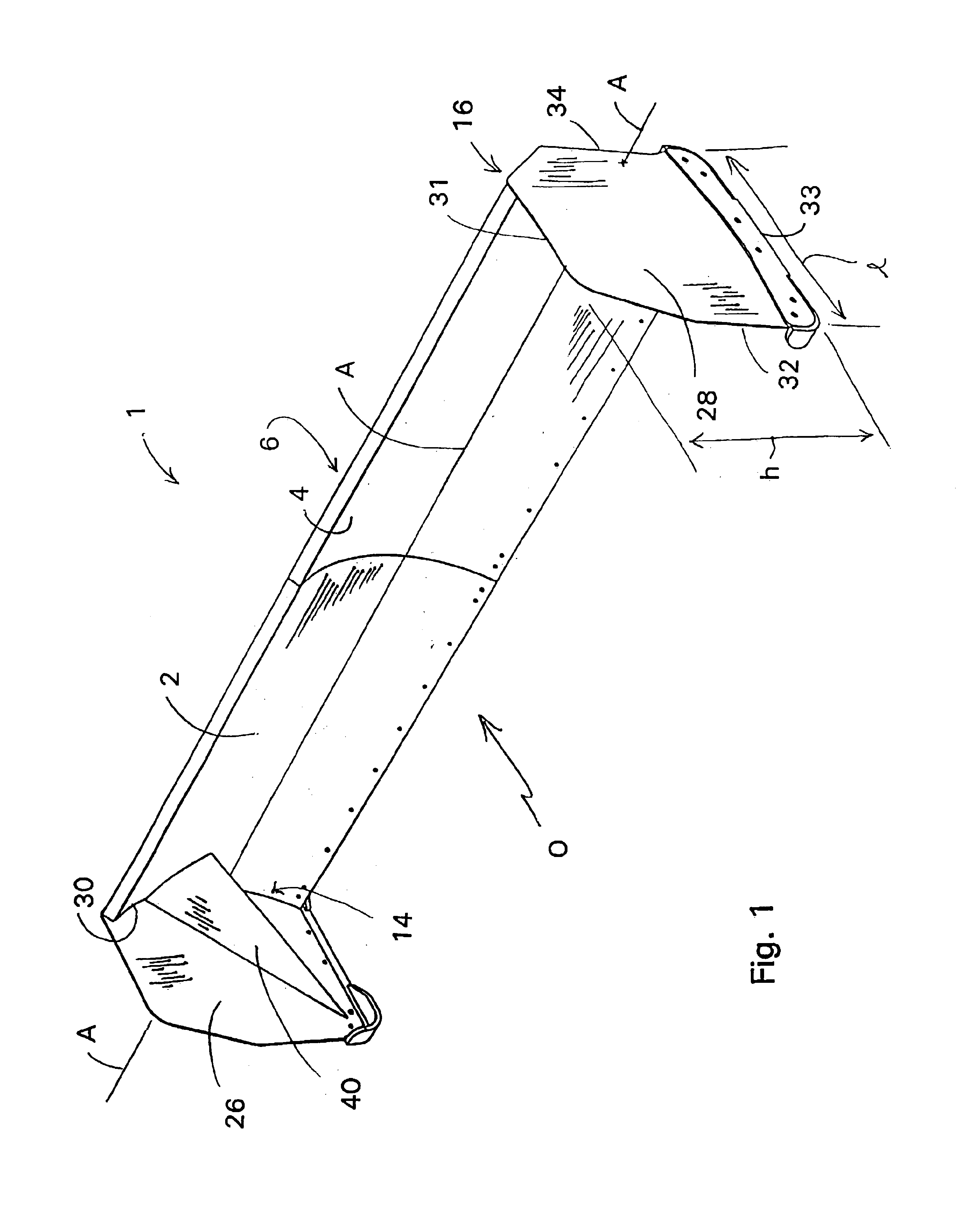
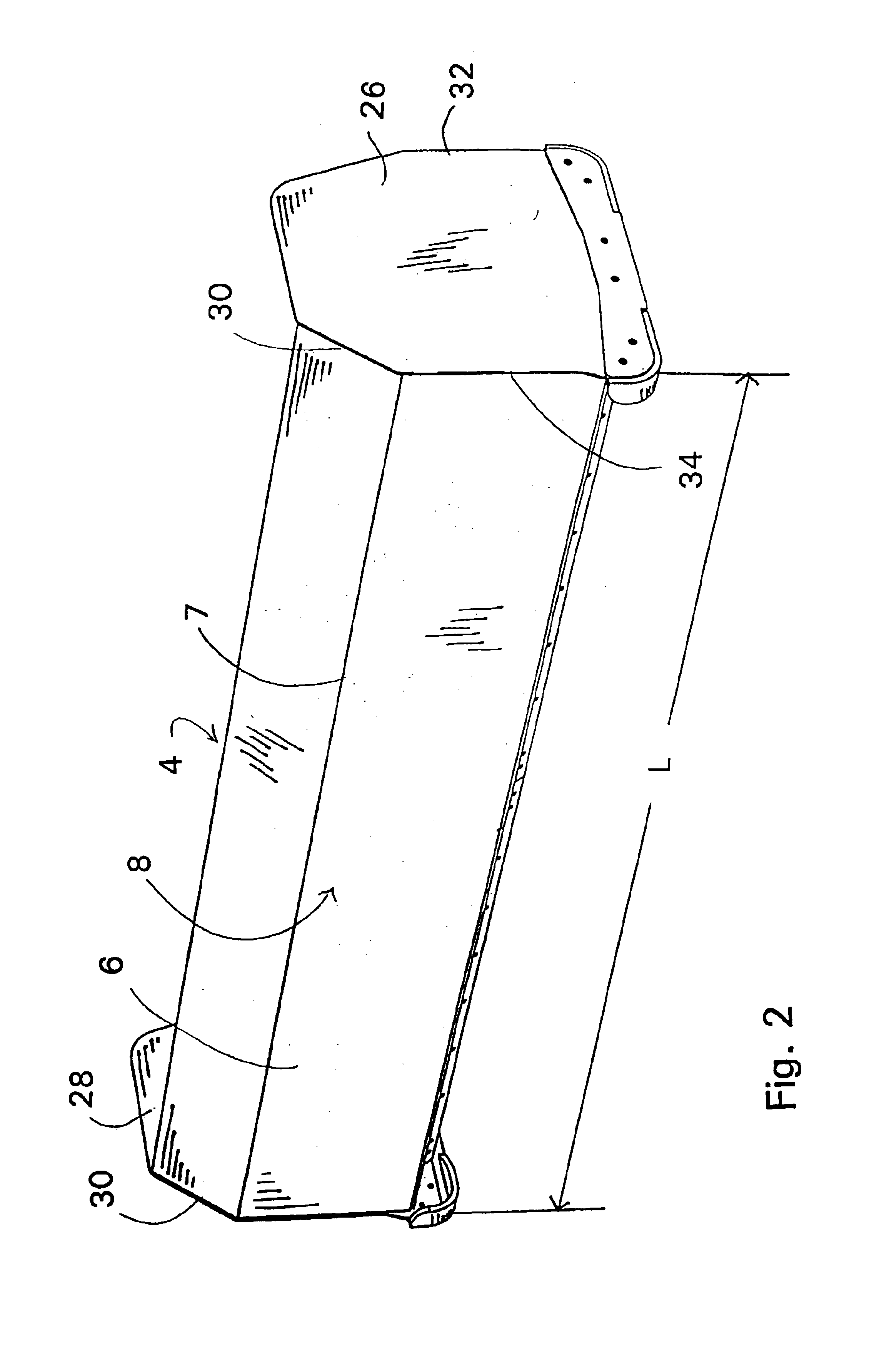
In conjunction with FIGS. 1 and 2, a brief description concerning the various components of the present invention will now be provided. As can be seen in this embodiment, the present invention provides a box blade 1 having main blade 2 extending along a longitudinal axis A for a longitudinal length L. The main blade 2 may be planar, i.e., flat, relative to the longitudinal axis A or curved and / or bent at an angle substantially about the longitudinal axis A running the longitudinal length L of the blade 1 to facilitate retention of materials being moved by the blade 1.

The main blade 2 has a front surface 4 for engaging material and a back surface 6 generally for supporting mounting hardware. The main blade 2 may be provided as either a single sheet of metal or, as shown in conjunction with FIG. 2, the main blade 2 may be a double walled design having a spaced apart front and rear wall 8, 10, respectively. A double walled design may include the front and rear walls 8, 10 having a subs...


PUM


Abstract

A materials pushing or moving blade for use with heavy equipment vehicles, for example, a bulldozer or loader, and more specifically to a method and apparatus for moving snow, specifically a snow moving blade having a reinforcing gusset for strengthening the extended sidewalls of the snow moving blade.

Description

FIELD OF THE INVENTIONThe present invention relates to a materials pushing or moving blade for use with heavy equipment vehicles, for example, a bulldozer or loader and more specifically to a method and apparatus for moving snow, specifically a snow moving blade having a reinforcing gusset for strengthening the extended sidewalls of the snow moving blade.BACKGROUND OF THE INVENTIONIn general, heavy equipment, for example, a bulldozer, loader, etc., for moving materials, e.g., earth, snow, refuse, etc., are provided with a main blade which is attached to a hydraulically articulated blade adjustment device on the vehicle. A general materials moving blade is a substantially planar, rectangular piece of steel which may have a substantially vertically oriented curve or bend along its length to facilitate materials handling and moving. It is also known that these blades may be divided into horizontally adjacent blade segments for materials handling purposes as well. The blades are also of...

Claims


Application Information

Patent Timeline
IPC IPC(8): E01H5/06E01H5/04E02F3/76E02F3/815
CPCE01H5/066E02F3/8157E02F3/8152
Inventor VENNARD, ROBERT G.TREMBLAY, JUSTIN L.EVANS, MILES M. E.
Owner DEGELMAN IND LP
Learn More