Cushion tire

a technology of friction tire and rim, which is applied in the field of friction tire, can solve the problems of reducing the braking performance of industrial vehicles, and the riding feeling becomes extremely uncomfortable at the vehicle running time, and achieves the effect of increasing the fitting force of the tire to the rim

Inactive Publication Date: 2005-01-25
FUKUYAMA GOMU KOGYO +1
View PDF20 Cites 42 Cited by
  • Summary
  • Abstract
  • Description
  • Claims
  • Application Information

AI Technical Summary

Benefits of technology

According to the fifth invention, since a number of grooves are formed in the inner circumferential surface, even if the rim dimensions are uneven due to manufacturing errors of the wheel, the grooves formed in the inner circumferential

Problems solved by technology

Therefore, only a small-sized brake can be housed in this inner circumferential space, resulting in a problem of reducing a braking performance of the industrial vehicle.
However, the spring constant increa

Method used


Image

  • Cushion tire
  • Cushion tire
  • Cushion tire

Examples


first embodiment

a cushion tire of the present invention will be described.

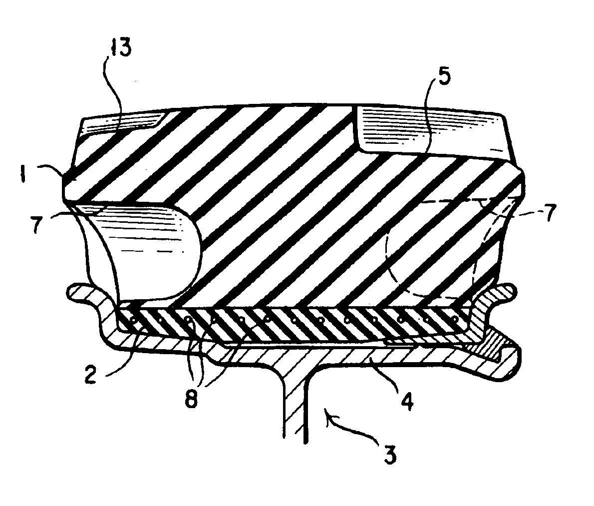
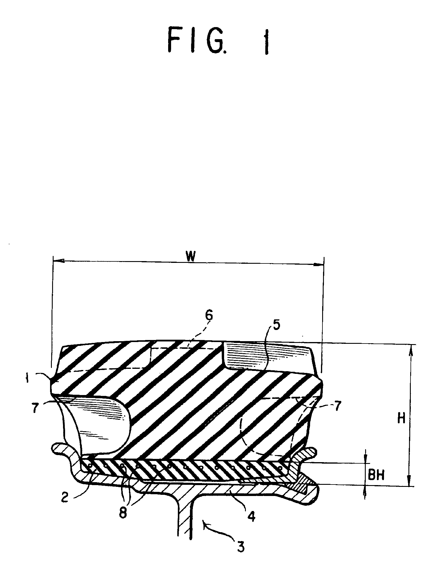
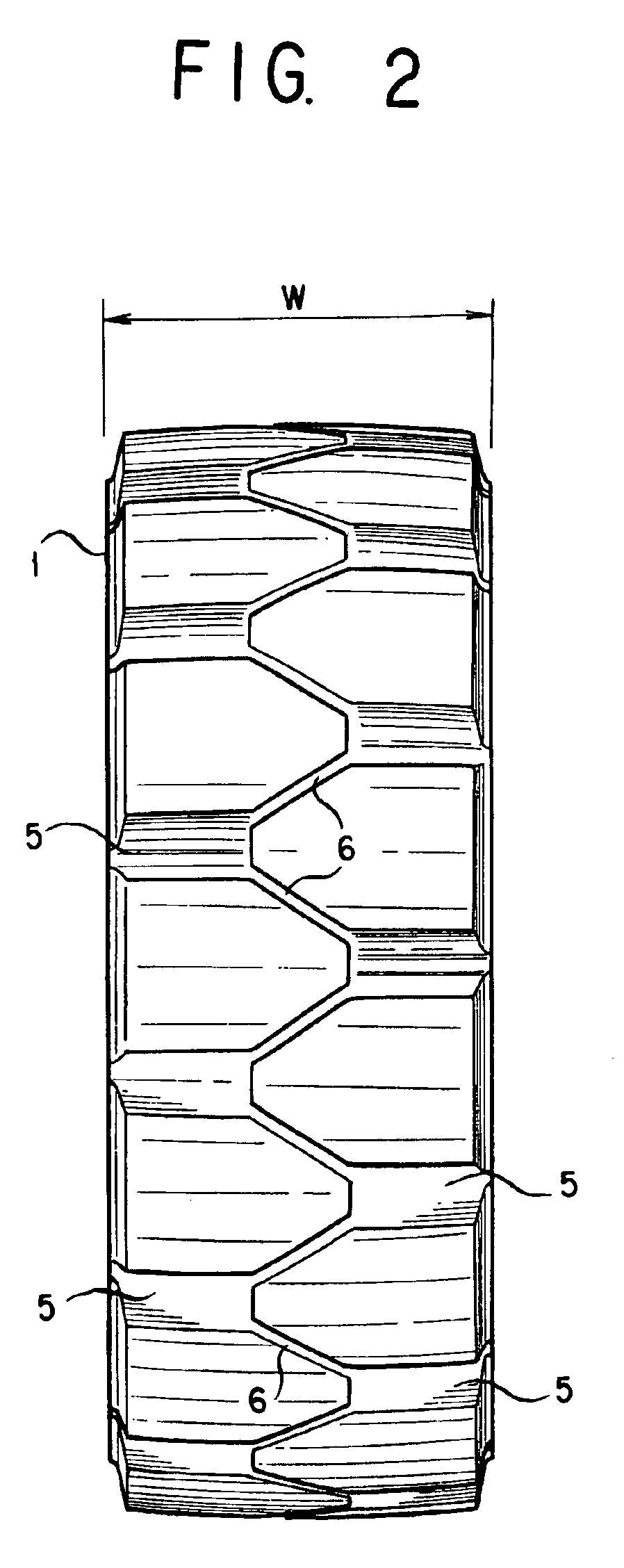
The cushion tire is, as shown in the sectional view of FIG. 1, formed from a rubber material without forming any airspace inside the tire so as to provide a double-layer structure including a tread rubber layer 1 disposed at an outer circumferential side, which is grounded, and a base rubber layer 2 disposed at an inner circumferential side which is fitted to a rim 4 of a wheel 3. Further, as shown in the entire front view of FIG. 2, a number of tread grooves 5 are formed in the outer circumferential surface which is grounded, and the leftside and the rightside tread grooves 5 in the tire width direction are disposed so as to be shifted from each other, by a half pitch, in the circumferential direction of the tire, and furthermore, the tread grooves 5 are connected to each other through fine connecting grooves 6, respectively. An aspect ratio (H / W), which is the ratio of a tire sectional height (H) to a tire width (W), is set...


PUM


Abstract

A cushion tire is formed from a rubber material without being provided with an airspace inside the tire. An aspect ratio, which is a ratio of a sectional height of a tire with respect to a width of the tire, is set to 15 to 80%. And a number of holes are formed in both bilateral side surfaces of the tire along a circumferential direction thereof.

Description

BACKGROUND TECHNOLOGY1. Technical Field of The InventionThe present invention relates to a tire for an industrial vehicle such as forklift truck, and more particularly, a cushion tire formed from a rubber material without forming any airspace inside the tire to thereby prevent a fear of blowouts.2. Description of Prior ArtIn an industrial vehicle such as forklift truck having a conventional structure, a large load is applied at a time of running at a low speed, and accordingly, in these days, a cushion tire formed from a rubber material, which has no inside airspace for preventing a fear of blowouts, has been widely utilized.As such a cushion tire, a pneumatic type cushion tire and a press-on type cushion tire have been generally known. The pneumatic type cushion tire has a double-layer structure, as shown in a sectional view of a tire of FIG. 15, in which a tread rubber layer 1 is disposed at an outer circumferential side of the tire and a base rubber layer 2 is disposed at an inne...

Claims


Application Information

Patent Timeline
IPC IPC(8): B60C7/12B60C7/10B60C7/00B29D30/02B29D30/00B60C7/24
CPCB29D30/02B60C7/10B60C11/0311B60C7/12Y10T152/10054Y10T152/10306B60C7/107B60C7/00
Inventor KATOH, YUSAKUODA, SATORUOZAKI, HIROTAKAFUJITA, NOBUOIKESUGI, FUMIOKAWASHIMA, KAZUOAOYAGI, TERUKI
Owner FUKUYAMA GOMU KOGYO
Why Eureka
Try Eureka