Load storage equipment

a technology for storage equipment and equipment, applied in the direction of charging manipulation, lighting and heating equipment, furniture, etc., can solve the problems of increasing construction costs, reducing the strength of the floor, and affecting the practical use of storage equipment, so as to achieve the effect of convenient construction

Inactive Publication Date: 2005-01-25
DAIFUKU CO LTD
View PDF10 Cites 335 Cited by
  • Summary
  • Abstract
  • Description
  • Claims
  • Application Information

AI Technical Summary

Benefits of technology

The object of the present invention is to provide compact load storage equipment that is easy to construct, and that can store loads on two or more stories.
A clean room may be formed on at least one of the stories. It is preferable that a housing be formed in the clean room and house in isolation the associated rotary rack and part of the transferrer. This keeps the purified atmosphere in the clean room from being contaminated with dust scattered by the operation of the rotary rack and the transferrer.

Problems solved by technology

This not only increases the cost of construction but also decreases the strength of the floor, making it difficult to put the storage equipment to practical use.

Method used


Image

  • Load storage equipment
  • Load storage equipment
  • Load storage equipment

Examples


first embodiment

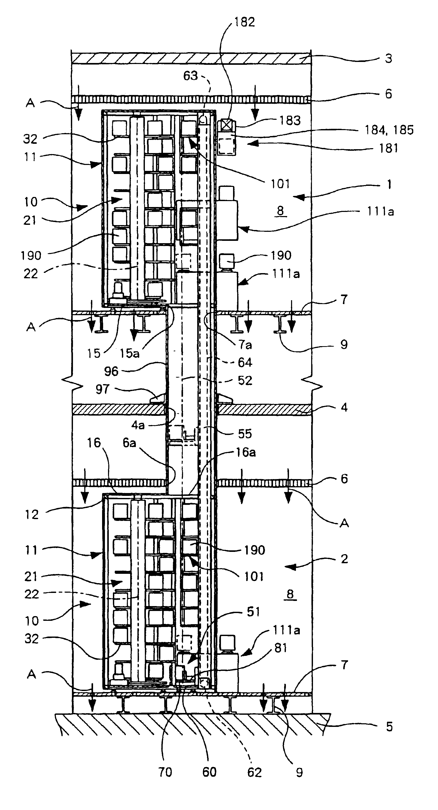
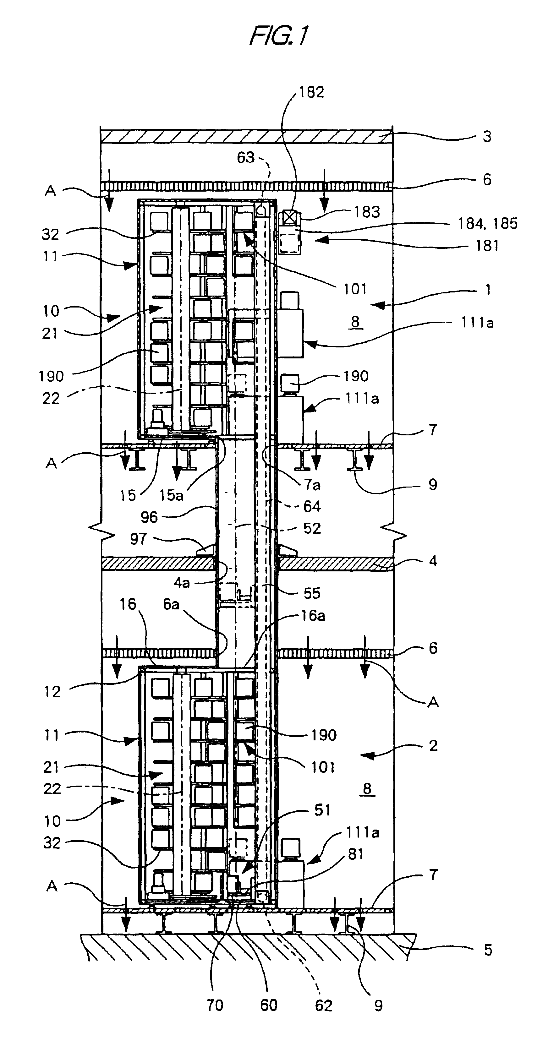
FIGS. 1-16 show load storage equipment according the present invention.

As shown in FIGS. 1-4, in an exemplary embodiment, an upper story 1 is defined between a ceiling slab 3 and an intermediate floor slab 4, and a lower story 2 is defined between the floor slab 4 and a base floor slab 5. On each of the stories 1 and 2, a clean room 8 is defined between a top filter plate 6 for air supply and a bottom grating or porous plate 7 for air release, which is supported by beams 9. The clean room 8 is kept clean on a downflow system, where clean air A is supplied through the filter plate 6 into the room 8, flows downward through the room 8 and is released from the room 8 through the grating plate 7.

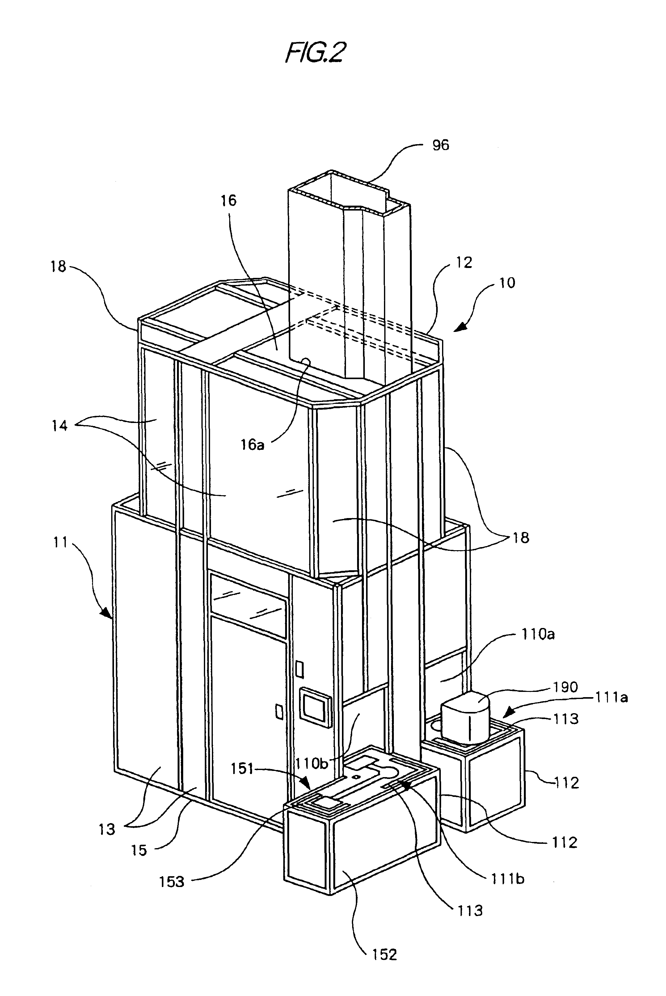
Each of the upper and lower clean rooms 8 houses a load storage apparatus 10. The upper and lower storage apparatuses 10 may be nearly identical in structure and each include a housing 11 in the form of a rectangular box, a rotary rack 21, four fixed racks 101, an inlet port 111a and an outlet po...


PUM


Abstract

Load storage equipment according to the present invention includes rotary racks 21, each of which is supported independently on a story 1 or 2, and which may not extend vertically through the slab 4 between the stories 1 and 2. The storage equipment also includes a transferrer 51 common to the rotary racks 21. Each of the rotary racks 21 can turn on a vertical axis 22 and includes load supports 32 arranged circumferentially around the vertical axis 22 and vertically. The transferrer 51 extends vertically near the sides of the rotary racks 21 and through the slab 4. The transferrer 51 includes a carrier 81, which can vertically move to carry loads to and from the load supports 32.

Description

FIELD OF THE INVENTIONThe present invention relates to load storage equipment for storing loads on two or more stories.PRIOR ARTAs an example, Japanese Patent Laid-Open Publication No. H10-98,094 discloses a conventional load storage equipment installed in clean rooms. The storage equipment includes a rectangular or square housing and a cylindrical rack, which is fitted in the housing. There is a grating floor between an upper clean room and a lower clean room. The grating floor has an opening, through which the housing extends.The cylindrical rack includes a cylindrical frame standing in the housing. The frame supports a number of vertically arranged stages of circumferentially arranged shelves or load supports. The rack has a port, through which loads can be moved into it and out of it. A transferrer is fitted in the center of the rack and includes a turntable, a guide post, a lift and a load holder. The turntable can be turned on a vertical axis. The post stands on the turntable ...

Claims


Application Information

Patent Timeline
Patent Type & Authority Patents(United States)
IPC IPC(8): B65G1/04B65G1/02B65G1/00B65G1/133B65G49/00H01L21/677
CPCB65G1/045B65G1/02
Inventor INUI, YOSHITAKA
Owner DAIFUKU CO LTD
Why Eureka
Try Eureka