
Gas turbine power generation facility

a technology of power generation facility and gas turbine, which is applied in the direction of fluid gearing, machine/engine, electric generator control, etc., can solve the problems of excessive electric torque generated in the generator, damage to the shear pin b>7/b> disposed to protect the motor, and momentarily and remarkably drop in voltage of the power receiving end, etc., to achieve shorten the installation length and recover in a short time

Inactive Publication Date: 2005-01-25
IHI CORP
View PDF13 Cites 14 Cited by
  • Summary
  • Abstract
  • Description
  • Claims
  • Application Information

AI Technical Summary

Benefits of technology

The present invention has been developed to solve the above-described problem. That is, an object of the present invention is to provide a gas turbine power generation facility which maintains an operation of the power generation facility and can secure a power supply of an important load during generation of an excessive torque in a generator by a momentary voltage drop, service interruption, and the like for a short time. Moreover, another object of the present invention is to provide a gas turbine power generation facility which can be downsized by shortening an installation length. Still another object is to provide a gas turbine power generation facility which can be recovered in a short time without damaging each shaft even with a torque exceeding an allowable torque of a transmission shaft. Still further object is to provide a gas turbine power generation facility whose operation is not stopped even with repeated generation of a relatively small momentary voltage drop.
For a fluctuation of an electric torque during the generation of the momentary voltage drop in a system, a momentary maximum generated torque sometimes reaches about six times a usual torque, a continuation time is remarkably short, the torque vertically fluctuates centering on an average torque in a period of 16 to 20 msec, and the usual torque is sometimes recovered in one or less second. Therefore, in order to prevent motors such as a gas turbine from being damaged by the momentary maximum generated torque, and maintain the operation of the power generation facility, the excessive electric torque of the generator needs to be attenuated before transmitted to the motor. That is, a fluctuating torque energy of a short time may be absorbed by a certain mechanism. The present invention is based on an inventive finding and idea.
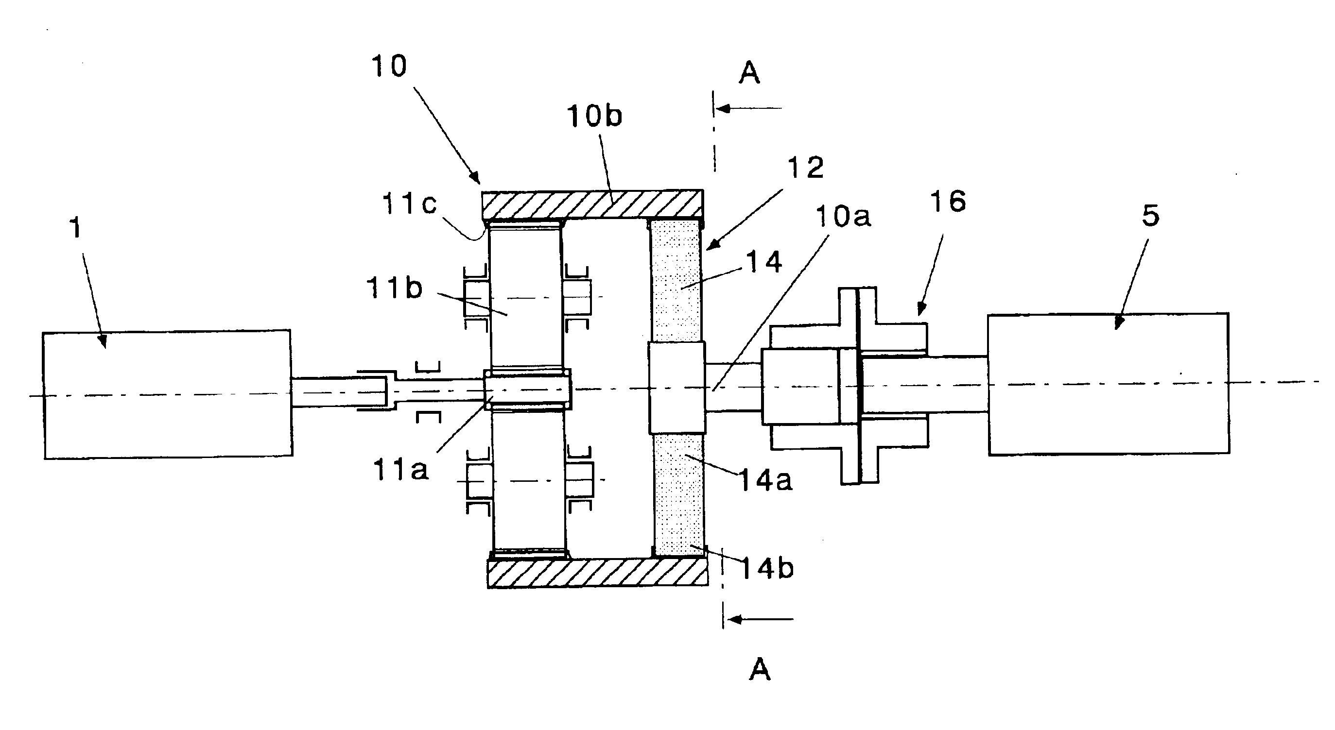
According to the constitution of the present invention, since the strain energy of the elastic deformation means (12) within the elastic limit is set to be larger than the fluctuation torque energy of the generator of the momentary voltage drop time, the momentary maximum generated torque of a short time elastically holds the strain energy therein, and discharges the energy during the generation of a torque of an opposite direction in a period of 16 to 20 msec. Therefore, the operation of the power generation facility can be maintained without transmitting an excessive torque to the gas turbine.
Furthermore, it is preferable to dispose a hydraulic torque limiter (16) between the output shaft (10a) and the generator (5). The hydraulic torque limiter may be of a type such that a pressure oil is held between the inner ring and outer ring, the pressure oil is discharged during application of a transient response torque not less than a set torque and the inner and outer rings freely rotate with respect to each other. This can prevent a shear pin from being cut by an accumulated metal fatigue and accordingly prevent the power generation facility from stopping.

Problems solved by technology

However, even when the apparatus is disposed, but when a parallel off speed is sufficiently fast, the voltage of a power receiving end momentarily and remarkably drops.
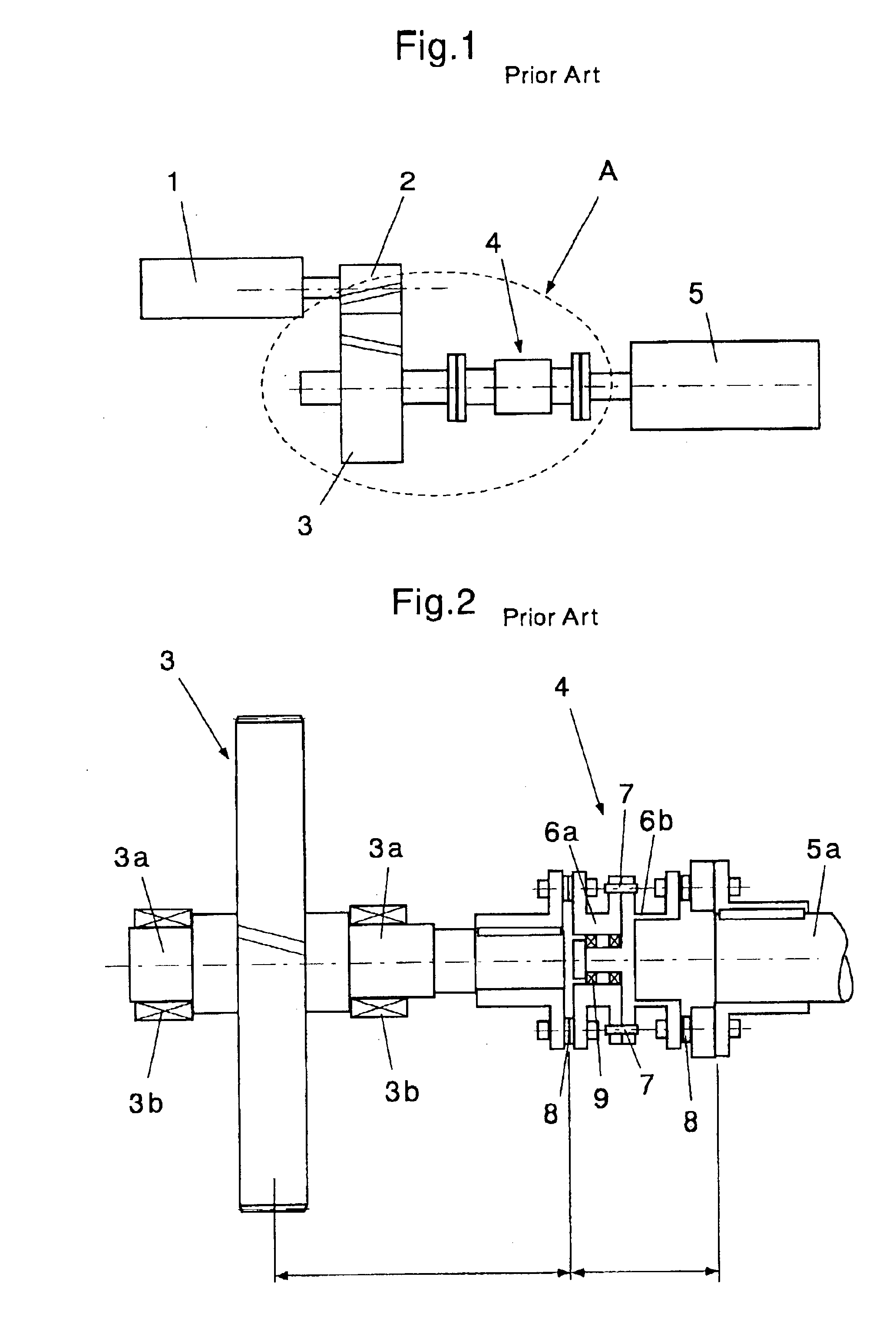
When the momentary voltage drop is generated in the system, an excessive electric torque is generated in the generator 5.
This causes a problem that the shear pin 7 disposed to protect the motor is damaged.
However, a short circuit accident of the generator, momentary voltage drop and service interruption on a system side, and the like generate the excessive electric torque in the generator.
When a transient response torque exceeds the allowable torque of the motor, the shear pin between the motor shaft and the generator shaft breaks, and there is a problem of much recovery time.
Moreover, there is a problem that the shear pin disadvantageously breaks by an accumulated metal fatigue even with a relatively small momentary voltage drop (10 to 30%).

Method used


Image

  • Gas turbine power generation facility
  • Gas turbine power generation facility
  • Gas turbine power generation facility

Examples


embodiment 1

[Embodiment 1]

An embodiment of the present invention described above will be described hereinafter based on a simulation result.

FIG. 7 is a characteristics diagram of elastic deformation means according to the present invention. This diagram shows a case in which the voltage drops by 100% because of the momentary voltage drop. Additionally, in this diagram, the abscissa shows a synthetic spring constant of power transmission means (coupling) for connecting the gas turbine 1 to generator 5. Moreover, the ordinate shows a response torque in a ratio to a rated torque of a steady time.

As shown in the drawing, for a maximum torque in a conventional shaft coupling, the shaft coupling indicates about 4.5, and a gas turbine output shaft (GT output shaft) indicates about 3.8. Moreover, from this drawing, it is seen that the synthetic spring constant is reduced (in a rightward direction in the drawing), the response torque can thereby be reduced, the synthetic spring constant (torsion spring ...


PUM


Abstract

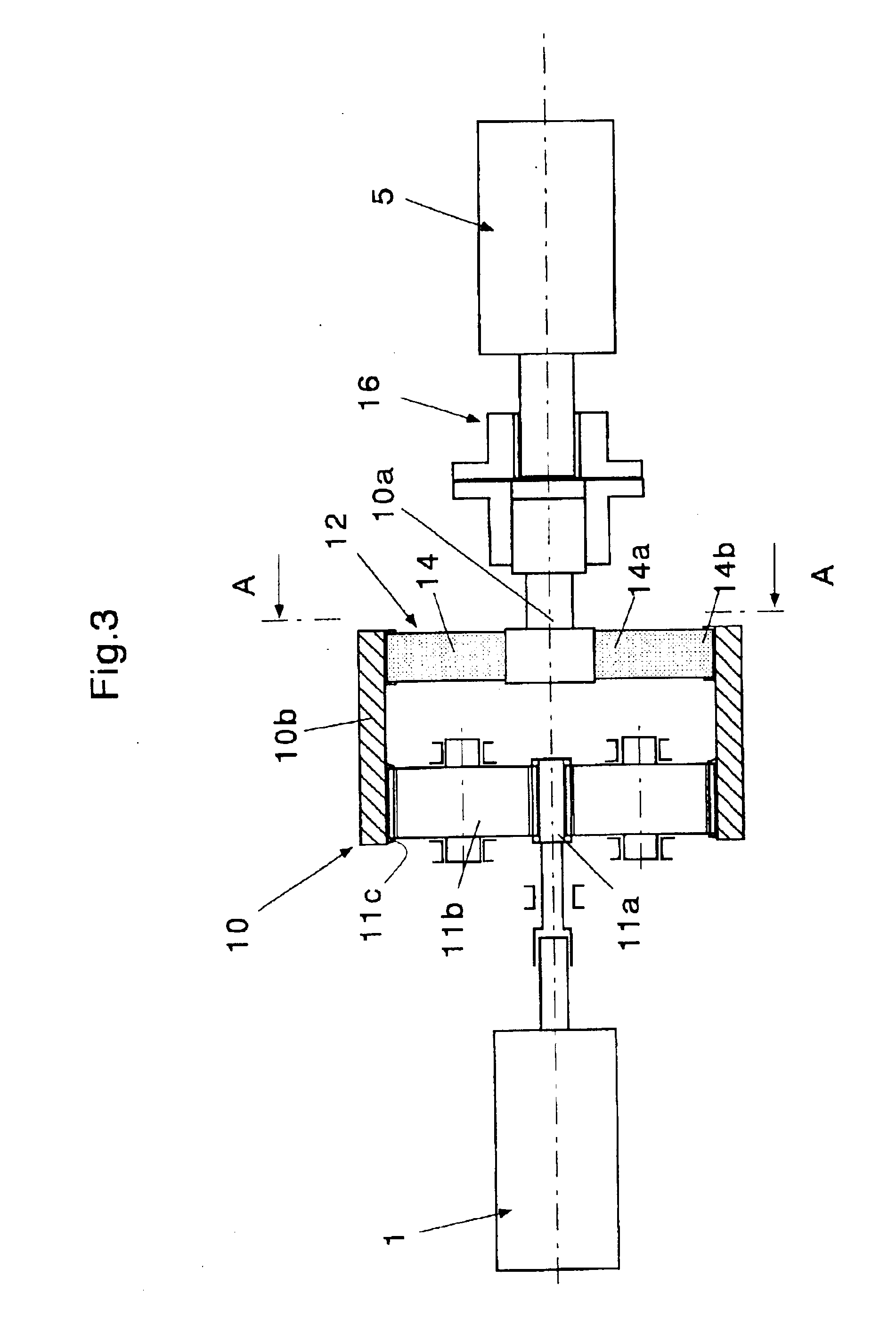
There is provided a planetary reduction gear 10 between a gas turbine 1 and a generator 5. The planetary reduction gear includes elastic deformation unit 12 on an output side, and for the elastic deformation unit, a strain energy within an elastic limit is set to be larger than a fluctuation torque energy of the generator of a momentary voltage drop time. The elastic deformation unit 12 includes an elastic member which elastically connects an output shaft 10a of the planetary reduction gear to an outer ring 10b. Thereby, when an excessive torque is generated in the generator by a momentary voltage drop, service interruption, and the like for a short time, it is possible to maintain the operation of a power generation facility, and secure a power supply of an important load, and an installation length is shortened and the facility can be downsized.

Description

This application is a 371 of PCT / JP02 / 03922 filed Apr. 19, 2002.BACKGROUND OF THE INVENTION1. Technical Field of the InventionThe present invention relates to a gas turbine power generation facility for maintaining an operation of the power generation facility, and securing a power supply of an important load, when an excessive torque is generated in a generator because of a momentary voltage drop or service interruption of a commercial power supply system.2. Description of the Related ArtWith an accident caused by a thunderstorm, and the like in a commercial power supply system, a phenomenon occurs that a voltage of a power line momentarily and remarkably drops. This voltage drop is referred to as a “momentary voltage drop”. In this case, in order to minimize a damage of a power generation facility and secure a power supply of an important load of a factory, an apparatus for detecting the accident at a high speed and disconnecting the commercial power supply system is disposed in s...

Claims


Application Information

Patent Timeline
Patent Type & Authority Patents(United States)
IPC IPC(8): F16D13/68F16F15/131F02C7/36F16F15/133F02C7/00F16D3/50F16D3/64F16D13/64F16H1/22F16H1/02H02K7/18B60L50/16F16D9/00F16F1/18F16H1/28H02P9/04H02P9/06H02P9/10
CPCB60L11/14F02C7/36B60L2270/145F16H1/227H02K7/1823Y02T10/641Y10T74/19656Y10T74/19684Y10T74/19651Y02T10/70Y10T74/19642Y10T74/19679Y02T10/7077B60L50/16Y02T10/64Y02T10/7072
Inventor AOKI, YOSHIAKI
Owner IHI CORP
Learn More