Drive unit for a laboratory centrifuge

a technology for laboratory centrifuges and drive units, which is applied in the direction of centrifuges, dynamo-electric machines, electrical apparatuses, etc., can solve the problems of unsuitable small centrifuges, unsuitable operating apparatuses, and unsuitable operating apparatuses, etc., to achieve safe and reliable separation, facilitate a particularly compact motor structure, and good damping

Inactive Publication Date: 2010-09-16
HANNING ELECTRO WERKE GMBH & CO KG
View PDF12 Cites 1 Cited by
  • Summary
  • Abstract
  • Description
  • Claims
  • Application Information

AI Technical Summary

Benefits of technology

[0008]In a more advanced embodiment of the invention, the motor drives a hollow shaft, which hollow shaft at least partially accommodates in its interior an inner shaft which is connected to the centrifuge rotor and which inner shaft is oscillatably or cantilever mounted. By means of elastic support means for the inner shaft, imbalances which occur due to nonuniform loading of the centrifuge rotor are effectively de-coupled from the remainder of the apparatus. In particular, vibrations are kept away from the motor bearings and supports and from the housing, thereby enabling high rotational rates to be achieved with the present drive unit. A compact structure is achieved in that the hollow shaft and inner shaft, to which inner shaft the centrifuge rotor is connected, are telescopically arranged, thereby reducing the installation length.
[0014]The motor has a stator assembly, and insulator plates for the stator end windings are provided on both sides of said stator assembly. The flattish end windings may be surrounded by insulating pieces, to facilitate a particularly compact structure of the motor, wherewith the separation distances of the insulating pieces can be kept small. Also, the insulating pieces allow electrical safety requirements to be satisfied, which require a safe and reliable separation between the motor and the contactable parts of the centrifuge. The insulation plates and insulating pieces comply with a requirement of double insulation between the stator winding and the rotor, in particular between the stator winding and the drive shaft assembly.
[0015]For particularly good damping of vibrations and suppression of wobbling, the spring stabilizer is comprised of an outer ring which is lodged against the hollow shaft and an inner ring which is lodged against the inner shaft. Thus, one or more spring elements are disposed, e.g. rotationally symmetrically around the axis. The inner ring may surround the inner shaft in a close fit, and may be in forcible engagement with the inner shaft. It is advantageous that the length of the spring stabilizer is greater than its diameter, preferably a multiple of the diameter.
[0016]In order to be able to absorb vibration of the inner shaft by the spring means provided, at least one spring stabilizer is disposed closer to the centrifuge rotor than the end of said inner shaft which end is fixed in the hollow shaft. Thus, the configuration of the spring stabilizer may depend on the length of the inner shaft and the weight of the centrifuge rotor. In any event, the combination of elastic inner shaft and spring stabilizers allows the centrifuge rotor to be displaced radially and enables effective suppression of wobbling movements of the centrifuge rotor, particularly such wobbling as may occur when the rotational rate is at certain “critical rotational speeds”. Thus the spring stabilizer has the desired stabilizing effect. Thereby vibration which can arise through imbalances in the loading of the centrifuge rotor are de-coupled from the bearing system of the hollow shaft and from the stator. Noise is reduced, and bearing stress is kept low.
[0018]Preferably the diameter of the inner shaft is small, 4-10 mm, particularly 5-8 mm. The small shaft diameter is attended by low thermal conduction, as a result of which the risk of heat influence on the samples is reduced.

Problems solved by technology

The configuration illustrated is somewhat costly, due to the configuration of the special electric motor.
However, the operating apparatus has a physically very long construction and is unsuitable for small centrifuges.
In addition, the elastic bearings cause “walk-through losses” which can only poorly be ameliorated.
The bearing structure is therefore thermally critical, limiting the rotational rate.
In an instance of wobbling of the centrifuge rotor, however, these support means are unable to stabilize the movement of the shaft.

Method used


Image

  • Drive unit for a laboratory centrifuge
  • Drive unit for a laboratory centrifuge
  • Drive unit for a laboratory centrifuge

Examples


Embodiment Construction

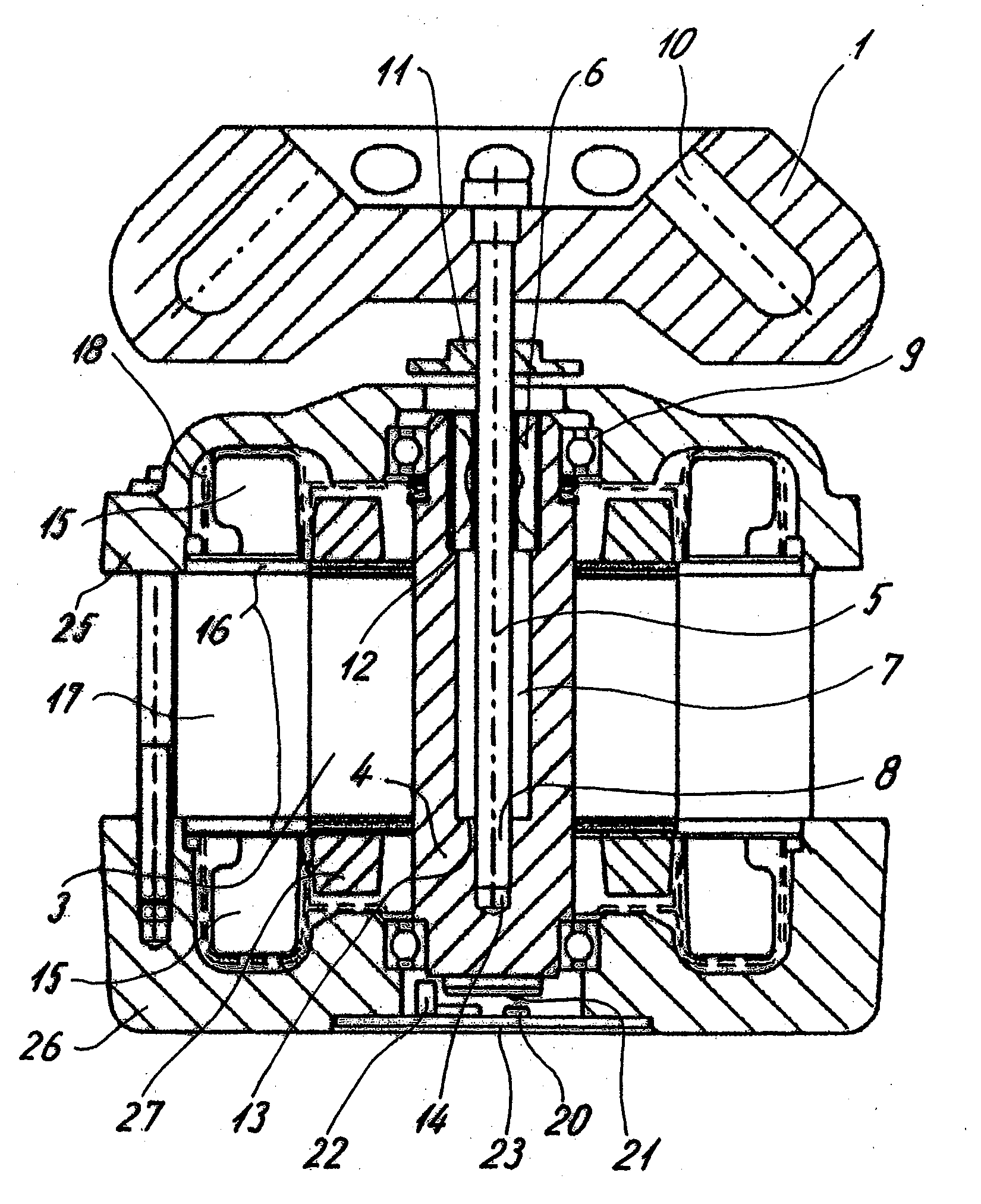
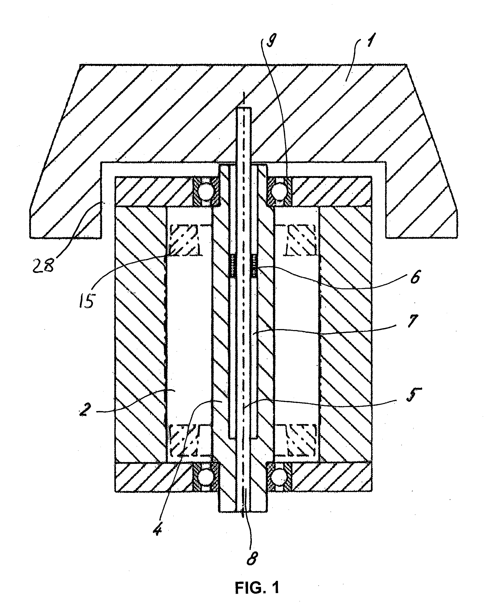
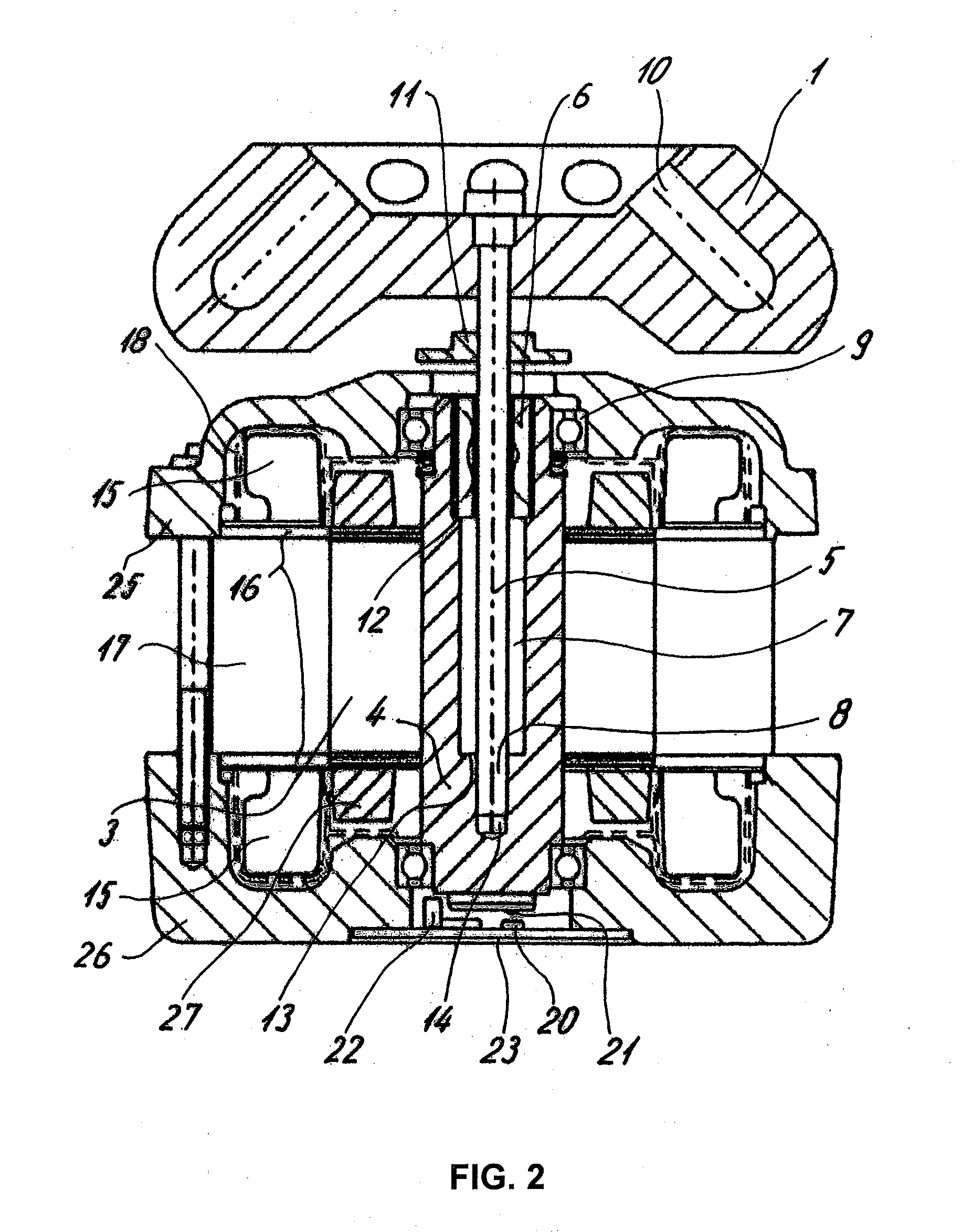
[0023]A laboratory centrifuge comprises a centrifuge rotor 1 in which samples can be disposed. The centrifuge rotor 1 is driven by a motor 2 which is shown only schematically in FIG. 1, which motor is disposed in a housing 3, shown in FIG. 2. The motor 2 drives a shaft, which may be a simple conventional solid shaft.

[0024]The drive unit and rotor for the laboratory centrifuge provide a compact structure, especially because an upper portion of a motor housing 3, and, preferably, an upper portion of a motor 2, e.g., at least a portion of the upper winding 15, is placed in a recess 28 of the centrifuge rotor. That is, for a centrifuge with vertical shaft, the upper end of the motor housing, preferably the upper end of the motor, is positioned higher than the lower end of the centrifuge rotor

[0025]In a more advanced design, the shaft may be a hollow shaft 4 which accommodates and holds inside it an inner shaft 5 of a lesser diameter. One end region 8 of the shaft 5 is disposed in a pres...


PUM


Abstract

A compact laboratory centrifuge including a centrifuge rotor and a drive unit for driving the centrifuge rotor. The drive unit includes a motor, a motor housing and a shaft. The centrifuge rotor is attached to and driven by the shaft. The centrifuge rotor includes a recess adapted to receiving the upper portion of the motor housing, which is positioned in the recess.

Description

BACKGROUND OF THE INVENTION[0001]The present invention relates to a drive unit for a laboratory centrifuge, comprised of a motor by which a centrifuge rotor attached to a shaft is rotated.[0002]EP 867226 A2 discloses a laboratory centrifuge in which a rotor is spring-loadedly mounted via a shaft. The shaft and bearing is connected to the stator via four spring elements. The spring elements are intended to avoid vibration of the stator of the electric motor. The configuration illustrated is somewhat costly, due to the configuration of the special electric motor.[0003]DE 10038060 A1 discloses a centrifuge with an imbalance compensation device. A shaft carries a centrifuge rotor on one end, and the shaft has compensating rings which support it at a plurality of locations. The elastic bearing system described allows noises, vibrations, and a certain amount of imbalances to be compensated. However, the operating apparatus has a physically very long construction and is unsuitable for smal...

Claims


Application Information

Patent Timeline
Patent Type & Authority Applications(United States)
IPC IPC(8): B04B9/14B04B9/00
CPCB04B9/04H02K7/16B04B9/12
Inventor SOETEBIER, ERICH R.RAUSKOLB, RUEDIGER
Owner HANNING ELECTRO WERKE GMBH & CO KG
Why Eureka
Try Eureka