Clamping mechanism

A technology of clamping and template, applied in the field of clamping mechanism, can solve the problems of troublesome installation and long clamping mechanism, and achieve the effects of easy installation and transportation, long service life and reliable clamping

Active Publication Date: 2017-02-08
SHENGBANG GRP +2
View PDF5 Cites 2 Cited by
  • Summary
  • Abstract
  • Description
  • Claims
  • Application Information

AI Technical Summary

Problems solved by technology

[0003] In order to solve the problem that the existing mold locking mechanism in the background technology is relatively long and troublesome to install, the present invention provides a mold locking mechanism

Method used


Image

  • Clamping mechanism
  • Clamping mechanism
  • Clamping mechanism

Examples


Embodiment Construction

[0018] Embodiments of the present invention will be further described below in conjunction with accompanying drawings:

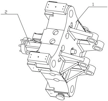
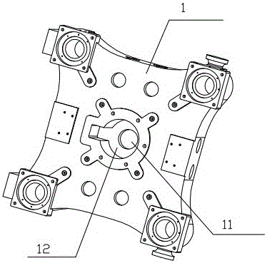
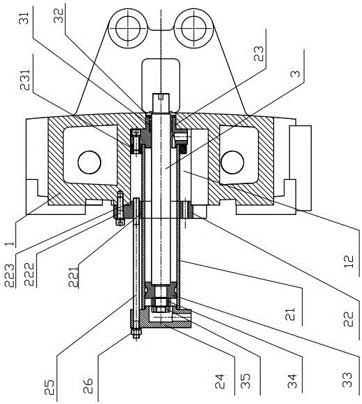
[0019] Depend on figure 1 combine figure 2 , 3 As shown, a mold clamping mechanism includes a mold adjusting template 1 and an oil cylinder 2. The mold adjusting template 1 is provided with a mold locking hole 11, and the rear surface of the mold adjusting template 1 is sunken inward to form an accommodating groove 12. , the cylinder 2 is provided with a mold clamping link 3 passing through the clamping hole 11 to be connected with the moving template, and the cylinder 2 is inserted into the accommodating groove 12 from the rear surface of the mold adjusting template 1 and It is fixed to the rear surface of the mold adjusting template 1 (with the side close to the moving template as the front surface, the same below), and the mold clamping link 3 passes through the mold locking hole 11 and is aligned with the cylinder 2 along the axis of the mold clamping...


PUM


Abstract

The invention provides a clamping mechanism and aims to solve the problem that an existing clamping mechanism is relatively long and is complicated in installation. The clamping mechanism comprises a die adjusting template and an oil cylinder; the die adjusting template is provided with a clamping hole; the rear surface of the die adjusting template is recessed inwards to form an accommodating groove; the oil cylinder is provided with a die assembly connecting rod which is connected with a movable template after passing through the clamping hole; the oil cylinder is inserted into the accommodating groove from the rear surface of the die adjusting template and is fixed to the rear surface of the die adjusting template; the die assembly connecting rod passes through the clamping hole and is in sliding fit with the oil cylinder along the axis direction of the die assembly connecting rod. The clamping mechanism provided by the invention has the beneficial effects that the die adjusting template is provided with the accommodating groove, and the oil cylinder is inserted into the accommodating groove, so that the installation length of the oil cylinder exposed from the rear side of the die adjusting template is greatly shortened, and the overall length of an injection molding machine or a die-casting machine is greatly reduced. The clamping mechanism provided by the invention also has the advantages of being simple in structure, reliable in action, long in service life, convenient to mount, dismount and maintain, small in floor area and the like.

Description

technical field [0001] The invention relates to an injection molding machine or a die-casting machine, in particular to a mold locking mechanism. Background technique [0002] Injection molding machine is also known as injection molding machine or injection machine. It is the main molding equipment for making thermoplastics or thermosetting plastics into various shapes of plastic products with plastic molding molds. It is divided into vertical, horizontal, and all-electric types. The injection molding machine heats the plastic, applies high pressure to the molten plastic, and makes it shoot out to fill the mold cavity. The die-casting machine is a series of industrial casting machines that hydraulically inject molten metal into the mold under pressure to cool and form it, and obtain solid metal castings after the mold is opened. It was originally used for die-casting characters. With the advancement of science and technology and industrial production, especially with the d...

Claims


Application Information

Patent Timeline
Patent Type & Authority Applications(China)
IPC IPC(8): B29C45/67B22D17/26
CPCB22D17/266B29C45/67
Inventor 姜洪朱远舱
Owner SHENGBANG GRP
Why Eureka
Try Eureka