
Reactively induced fragmentating explosives

Inactive Publication Date: 2005-01-25
NAVY AS REPRESENTED BY THE SEC OF THE UNITED STATES OF AMERICA THE
View PDF10 Cites 46 Cited by
  • Summary
  • Abstract
  • Description
  • Claims
  • Application Information

AI Technical Summary

Benefits of technology

It is a further object of this invention to provide a formulation that when subjected to a weak shock i

Problems solved by technology

When the explosive detonates, the high pressures generated fracture the metal and launch the resulting fragments at high velocity.
This uniformity of the explosive structure imposes limitations on its performance.
For example, an explosive charge mostly composed of HMX (Cyclotetramethylenetetranitramine) is good for fragmenting metal cases and driving the fragments at high velocity, but it will perform less than optimum in internal blast applications.
That is because to drive fragments well, the explosive has to release a large amount of gases fast, but a good internal blast explosive has to be rich in fuels that react with the air contained inside the target, an intrinsically slow process.
HMX and Al (Aluminum) particles can be uniformly mixed to create a good internal blast explosive, however, that would not be optimal for fragmenting metal and driving the fragments at high velocity.
Moreover, the traditional deign of a fragmenting warhead whereby the metal shell surrounds the explosive imposes limitations.
However, no explosive is currently formulated by consolidating macroscopic fragments, each fragment being itself a complete explosive formulation, instead of the traditional method of consolidating microscopic particles in which case by definition the particles are uniformly distributed throughout the resulting explosive.
And no warhead design is currently capable of adjusting on demand the velocity of the fragments as well as optimally achieve substantially different outputs, such as high velocity fragments and a strong internal blast, simultaneously.

Method used


Image

  • Reactively induced fragmentating explosives
  • Reactively induced fragmentating explosives
  • Reactively induced fragmentating explosives

Examples


first embodiment

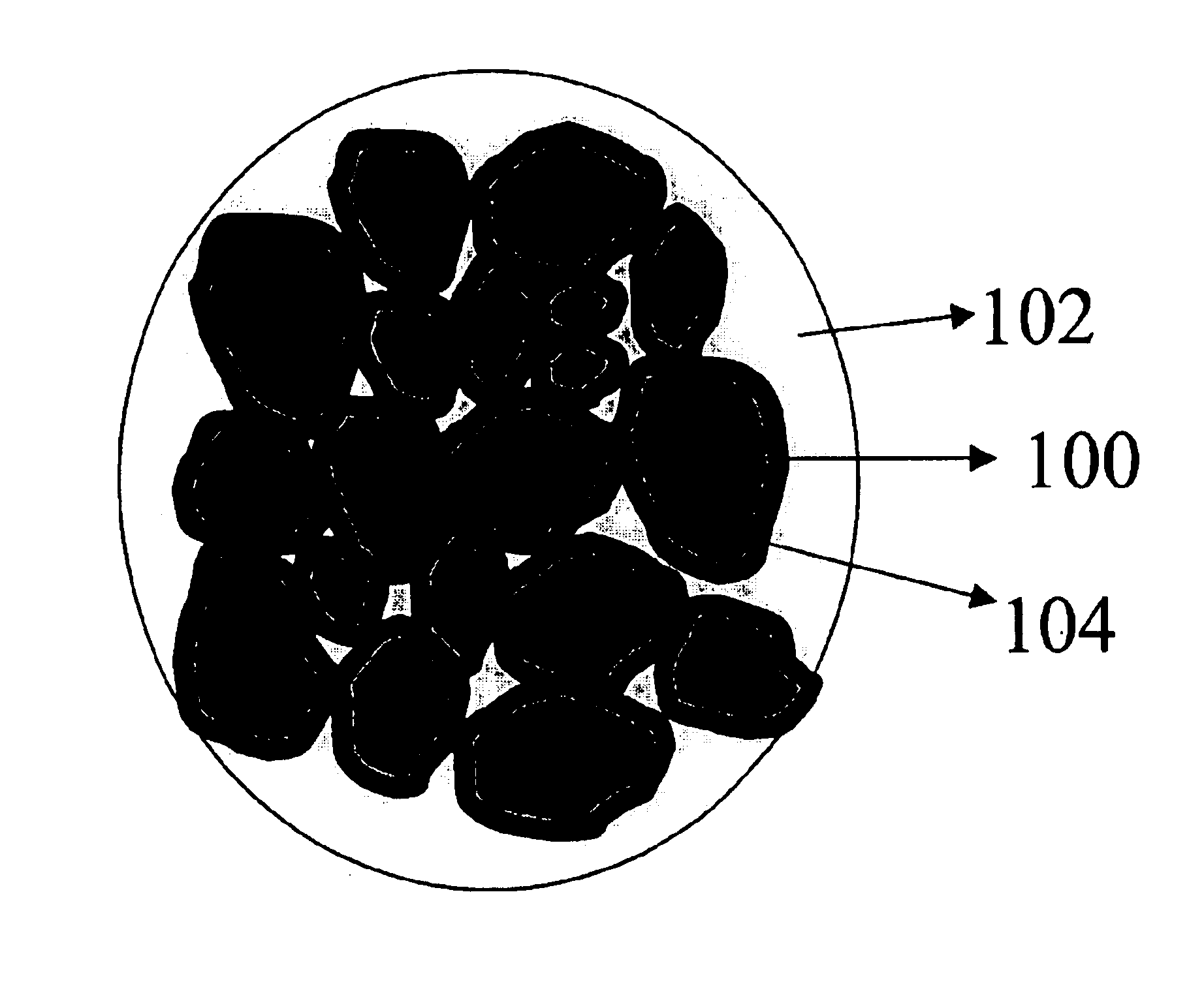
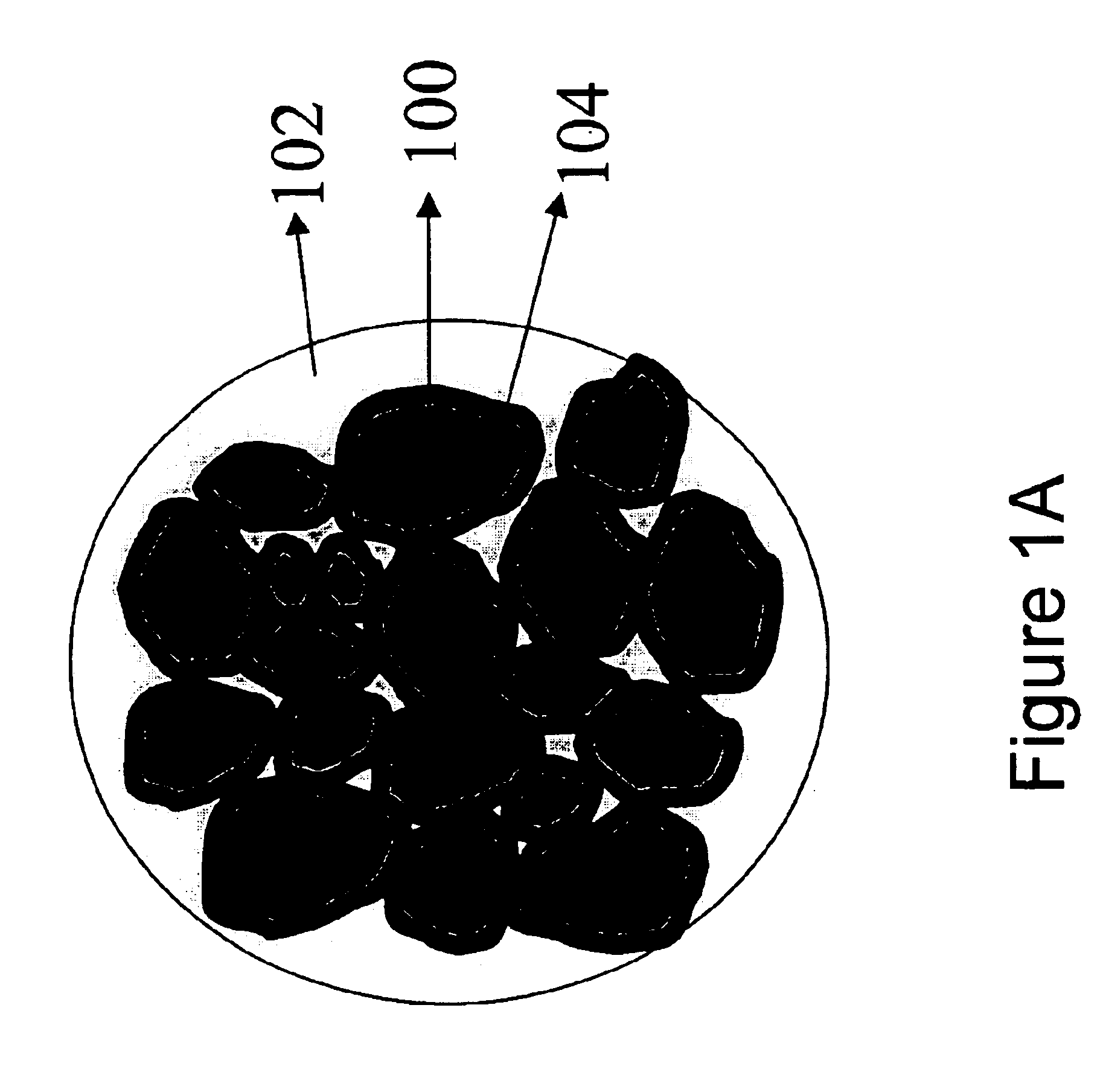
There are three basic embodiments of the above described formulation that may be employed in numerous configurations. The first embodiment, illustrated in FIG. 1A, includes a base material 102 comprising an explosive material that is more shock sensitive than the fragments 100. In this embodiment, the fragments 100 are shock insensitive, but heat sensitive so that a weak shock detonates the base material 102 with the resulting hot gases from said detonation starting the surface of the heat sensitive fragments 100 to burn.

second embodiment

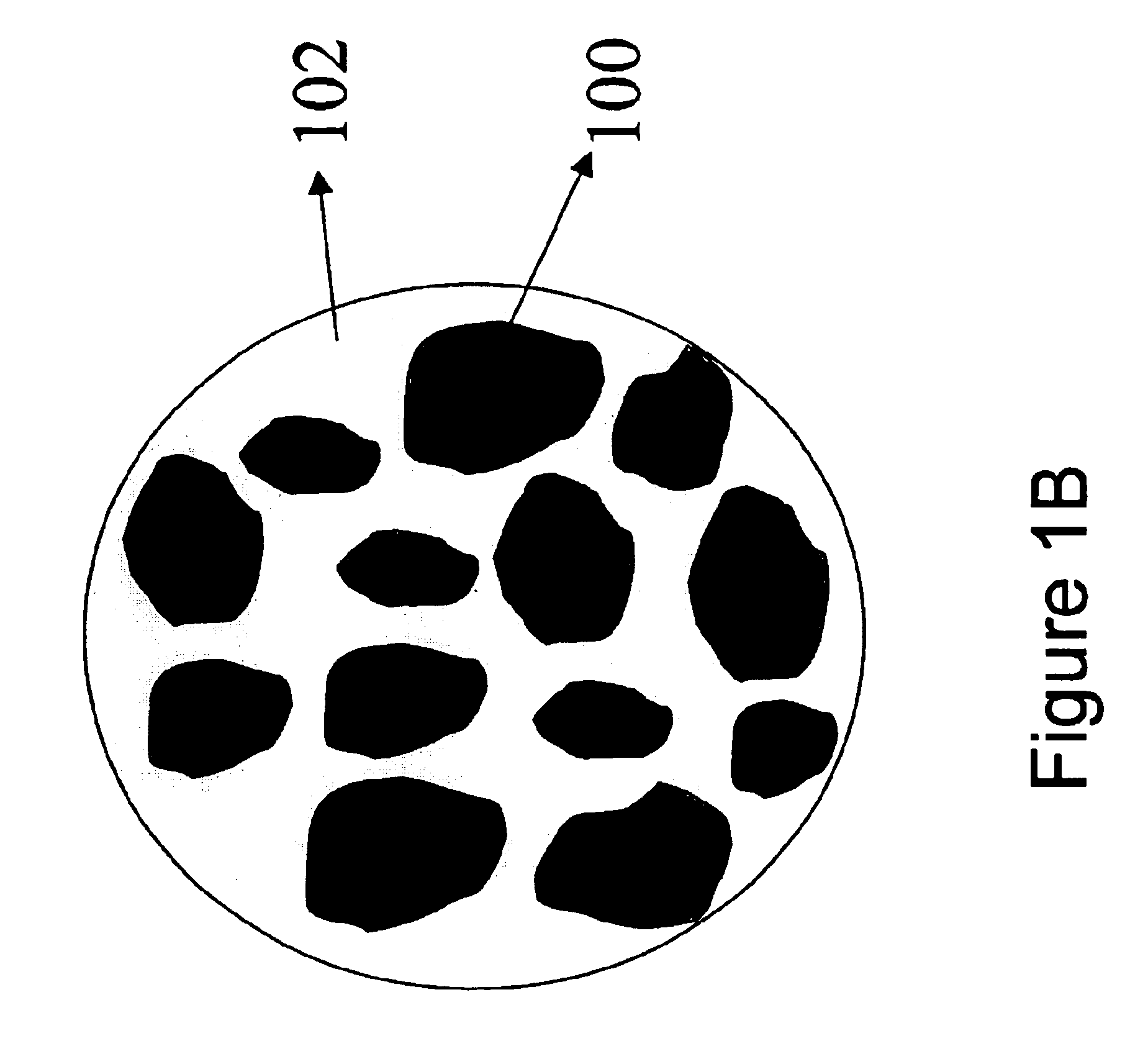
In the second embodiment, illustrated in FIG. 1B, the base material 102 also includes an explosive material that is more shock sensitive than the fragments 100. However, the fragments are not heat sensitive enough for their surface to be reliably ignited by the hot detonation products of the base material. Therefore, a heat sensitive, but shock insensitive explosive material is used to coat 104 the fragments 100 to ensure ignition.

The final embodiment, illustrated in FIG. 1C, comprises shock-insensitive fragments 100 that are heat sensitive, coated 104 with an explosive material that is shock sensitive. The base material 102 filling the interstitial spaces comprises an inert material that simply holds the fragments together. Therefore, in this configuration, the base material 102 would comprise a substantially smaller fraction of the overall mass / volume of the formulation than in the embodiments described above. When a weak shock is applied to this embodiment, the coating explosive ...


PUM


Abstract

The invention, as embodied herein, comprises a new composition that provides different outputs depending upon the level of stimulus supplied to the composition. More specifically, if the composition is subjected to a weak shock, the composition produces fragments that burn upon their surfaces. If the composition is subjected to a strong shock, the bulk of the fragments will initiate, and, depending upon the make-up of the fragments, an explosive, propellant, or pyrotechnic, a different output will result.

Description

BACKGROUND OF THE INVENTION1. Field of the InventionThis invention relates in general to explosive formulations, more particularly to composite solid explosive formulations, and even more particularly to composite solid explosive formulations that fragment instead of detonating when subjected to a weak shock, but fully detonate when subjected to a strong shock. The present invention also relates to several applications of said explosive formulations. These incude composite solid explosives with an adjustable yield, thermobaric explosives, and explosives specifically tailored to chemically damage electronic equipment.2. Description of the Related ArtIn general, composite explosives are currently formulated by combining several components, all in powder form, but with at least one component capable of binding the others. In the case of pressed explosives, for example, a small fraction of wax or viton is added to the other energetic components and the mixture pressed. In the case of me...

Claims


Application Information

Patent Timeline
IPC IPC(8): C06B45/02C06B45/18C06B45/00
CPCC06B45/00C06B45/02F42B12/50F42B12/32C06B45/18
Inventor GUIRGUIS, RAAFAT H.
Owner NAVY AS REPRESENTED BY THE SEC OF THE UNITED STATES OF AMERICA THE
Learn More