
Powder jet device for dispensing dental material

a technology for dental materials and jets, applied in dental tools, dental surgery, medical science, etc., can solve the problems of severe constructional modifications, and achieve the effects of easy selection, easy change of operation positions, and reduced construction costs

Active Publication Date: 2018-05-22
3M INNOVATIVE PROPERTIES CO
View PDF101 Cites 0 Cited by
  • Summary
  • Abstract
  • Description
  • Claims
  • Application Information

AI Technical Summary

Benefits of technology

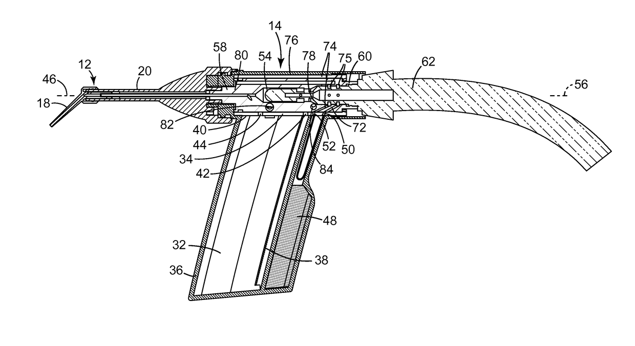
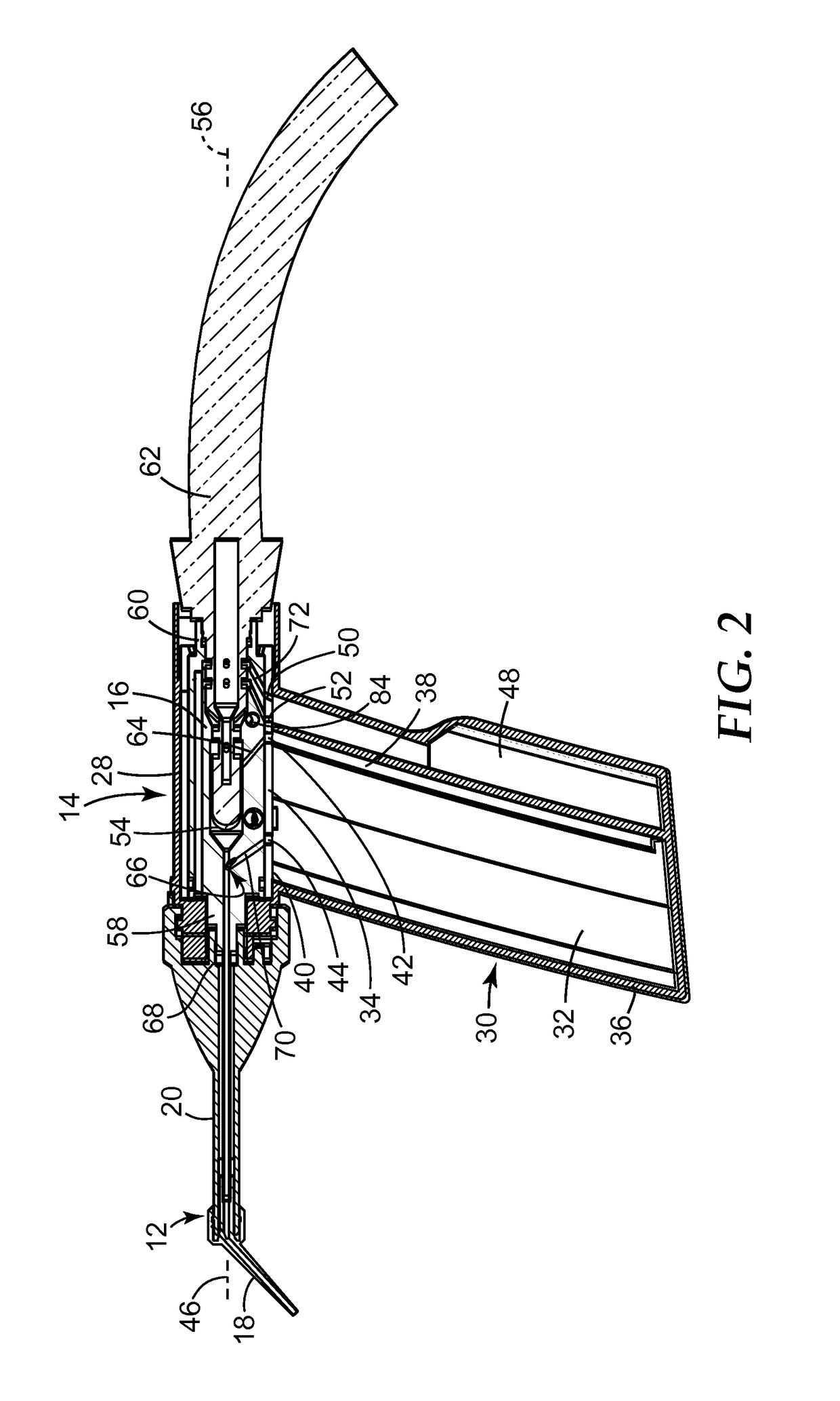
[0010]The present invention may be advantageous in that the powder jet device essentially consists only of three parts, for example the nozzle head, the housing and the valve member, such that the manufacturing costs are relatively low. Particularly, these three parts may be at least partially (and preferably entirely) made of plastics such that the manufacturing costs may be minimized. Further, because the fluid channel extends substantially between the distal end and the proximal end into the first chamber, the powder within the first chamber is completely dispersed because the fluid is enabled to pass substantially all of the powder. Particularly, the fluid may pass the powder from the bottom to the top if the powder jet device is held with the chamber portion generally vertical with the distal end of the chamber portion downwards and the proximal end upwards. In this orientation of the chamber portion the powder due to gravity tends to flow toward the distal end of the chamber portion where the fluid may enter the first chamber. Therefore the fluid can pass substantially all of the powder present in the first chamber in a direction against the direction of gravity. Thus the powder may be consistently aerated and kept in flow, and blocking of the powder may be avoided.
[0030]In one embodiment of the present invention the powder jet device has a housing with one or more chambers. For example, a chamber for a cleaning powder, a chamber for a polishing powder and a chamber for a disinfection liquid may be provided. Any chamber or combination of one or more chambers with each other for operation of the powder jet device may be selected centrally by the rotary valve. The rotary valve can preferably be actuated by use the rotary nozzle head. For example, the nozzle head may comprise a rotary knob, which is adapted to rotate the valve member if actuated by an operator. Further, as the fluid channel extends from the proximal end to substantially the distal end, the powder within the first chamber is reliably dispersed as the fluid passes the powder from the distal end towards the proximal end after entering the first chamber. This effect is combined with a venturi effect created by another part of the fluid flowing within the second fluid path. Accordingly, there are two flows of the fluid. The first flow enters the first chamber through the fluid channel and creates the dispersion. The second flow flows through the second fluid path and sucks the dispersion out of the first chamber based on the venturi effect.

Problems solved by technology

Particularly, some powder materials, when delivered through a nozzle of a powder jet device, may tend to block the nozzle.
After delivery, remaining media get in contact within the nozzle and still cause clogging.
However, this approach involves severe constructional modifications.

Method used


Image

  • Powder jet device for dispensing dental material
  • Powder jet device for dispensing dental material
  • Powder jet device for dispensing dental material

Examples


Embodiment Construction

[0039]The device 10 shown in the drawings is a powder jet device of a type for use in the dental field for applying a powder / gas mixture and a liquid to the tooth structure of a patient.

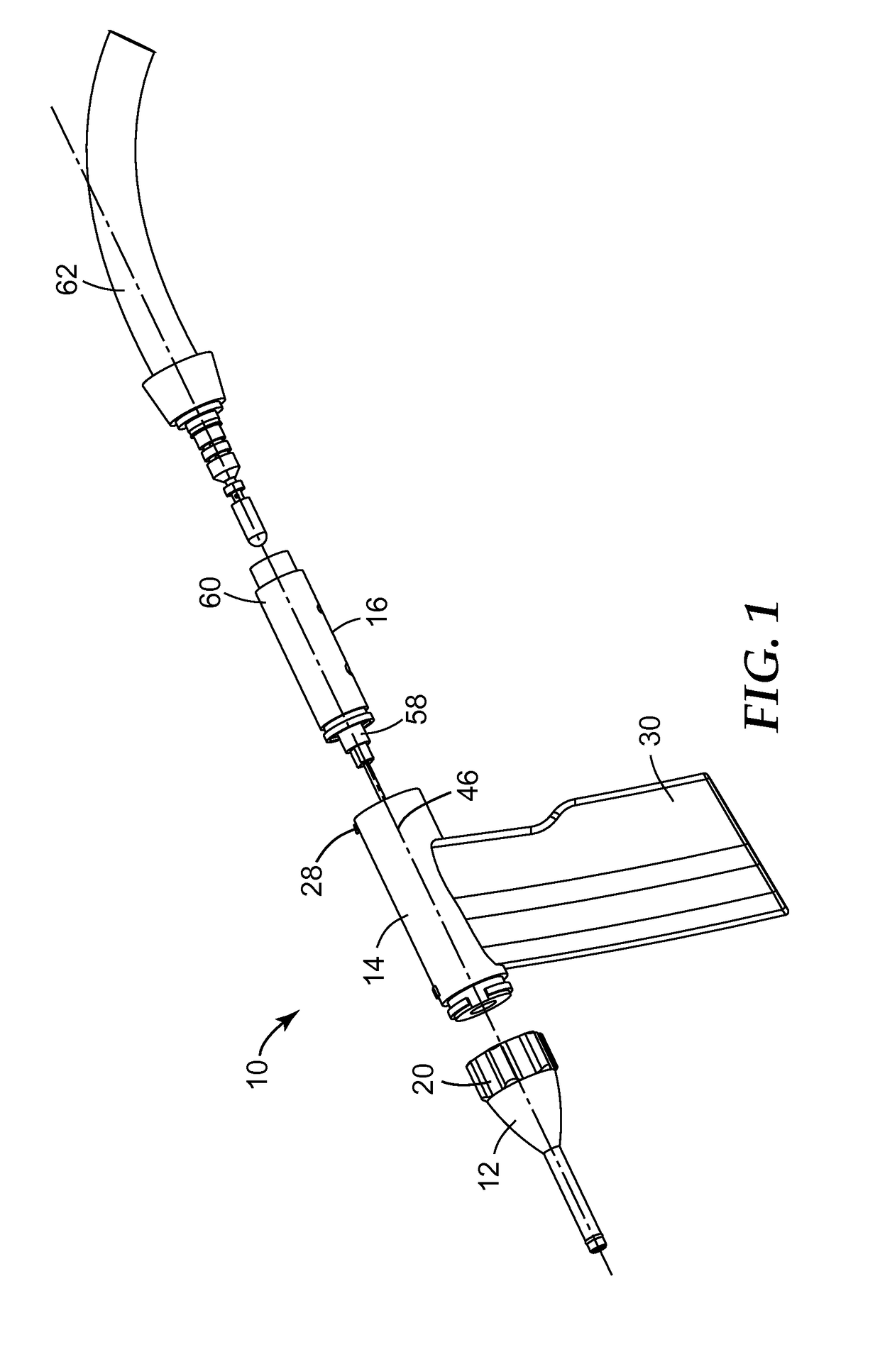
[0040]FIG. 1 shows an explosion view of a powder jet device 10 for dispensing a dental material according to the present invention. The powder jet device comprises a nozzle head 12, a housing 14 and a valve member 16. The nozzle head 12 comprises a discharge nozzle 18 (FIG. 2). The nozzle head 12 further comprises a rotatable knob 20. The rotatable knob 20 is adapted to rotate the valve member 16 as will be explained in more detail below. The nozzle head 12 may be designed such that an operator holding the nozzle head 12 or the housing 14 may rotate the knob 20.

[0041]FIG. 5 shows a longitudinal cross-section of the nozzle head 12. The nozzle head 12 comprises a first discharge channel 22 and a second discharge channel 24, which are disposed parallel, in particular preferably coaxial, to one another. ...


PUM


Abstract

A powder jet device (10) for dispensing a dental material comprises a nozzle head (12) comprising a discharge nozzle. The powder jet device (10) further comprises a housing (14) comprising a valve portion (28), which is connected to the nozzle head (12) and is adapted to receive a valve member (16), and a chamber portion (30) comprising at least a first chamber (32) for storing a powder material. The chamber portion (30) comprises a proximal end (34) located adjacent the valve portion (28), a distal end (36) located away from the valve portion (28) and a fluid channel (38) extending from the distal end (36) substantially to the proximal end (34) into the chamber. The powder jet device (10) further comprises a valve member (16) disposed within the valve portion (28). The valve member (16) comprises a fluid supply passage (54) and is movable between a first position, in which a first fluid path (64) for delivery of a fluid from the fluid supply passage (54) into the chamber via the fluid channel (38) so as to create a dispersion from the powder material and a second fluid path (66) for delivery of the dispersion to the discharge nozzle are open, and a second position, in which at least the first fluid path (64) is closed.

Description

FIELD OF THE INVENTION[0001]The present invention relates to a device for dispensing a dental material to a desired location, for example the tooth structure of a patient, and more particularly to a powder jet device.BACKGROUND ART[0002]In dentistry powder jet devices are currently used for applying a fluid stream of abrasive particles, air and water to the tooth structure of a patient, for example for cleaning or pretreating the tooth surfaces.[0003]Generally, a powder jet device may comprise a nozzle head through which the fluid stream can be delivered. Typically the fluid stream contains powder particles which are dispersed and entrained by an air stream guided through a powder containing chamber, and a liquid optionally added to the air / powder mixture, for example through a separate nozzle. In a device of that type used for cleaning tooth surfaces the powder material often comprises dental abrasive particles, and the liquid is normally water.[0004]Examples of powder jet devices ...

Claims


Application Information

Patent Timeline
Patent Type & Authority Patents(United States)
IPC IPC(8): A61C3/025A61C1/00A61C1/08
CPCA61C3/025A61C1/087A61C1/0084
Inventor PAUSER, HELMUT
Owner 3M INNOVATIVE PROPERTIES CO
Learn More