Edge insulating member for electrode plate, method of locking and unlocking the edge insulating member, and edge insulating member installation jig

a technology of edge insulating member and electrode plate, which is applied in the direction of electrical-based machining electrodes, instruments, manufacturing tools, etc., can solve the problems of excess cost generation, complex work, and deterioration of the quality of the refined material obtained during the electrolytic refinement process, and achieve the effect of easy removal

Inactive Publication Date: 2005-01-25
MITSUBISHI MATERIALS CORP
View PDF7 Cites 2 Cited by
  • Summary
  • Abstract
  • Description
  • Claims
  • Application Information

AI Technical Summary

Benefits of technology

The present invention has been conceived in order to resolve the problems, and its objective is, with an edge insulation member of an electrode plate which is used in an electrolytic refining process:(1) to facilitate its removal from and fitting to the electrode plate;(2) to be able to enhance its secure engagement to the electrode plate, to be able completely to insulate the edge portion of the electrode plate, and to be able to maintain this quality of secure engagement over a long time period;(3) to enhance the strength of the anti impact characteristic and the like;(4) to make the work of ablation of the electrodeposited cathode material from the electrode plate during the electrolytic refinement process easier; and(5) to eliminate mixing of material generated from the edge insulation member into the electrodeposited cathode material, in order to obtain a refined material with good product quality.
According to this type of edge insulation member, it can be easily removed from and attached to the electrode plate, and it is possible to enhance the secure engagement state between the edge insulation member and the electrode plate, and it is possible to increase the quality of insulation of the electrode plate edge portion.
Furthermore, the main body of the edge insulation member and the fitting jig may be made from resin, with the stopper being made from an elastomer whose elasticity is higher than the resin which is used for the main body and pin. By in this manner using a resin for the fitting jig and using an elastomer whose elasticity is high for the stopper, it is possible to enhance the quality of secure engagement between the stopper and the pin, and the quality of secure engagement between the stopper and the electrode plate, and it is possible strongly to fix the edge insulation member to the electrode plate. Yet further since it is possible to absorb deviation between the electrode plate and the edge insulation member which is caused by stress which is experienced when fixing the edge insulation member or when ablating electrodeposited cathode material or the like, or deviation between those two elements which is caused when the temperature is high during electrolysis due to differences in the coefficients of thermal expansion between the electrode plate and the edge insulation member, by the stopper, accordingly it is possible to maintain the secure engagement together of the edge insulation member and the electrode plate over a long time period.
According to this type of fixing method for an edge insulation member to an electrode plate, the fixing of the edge insulation member to the electrode plate is easy, and it is possible to increase the quality of secure engagement between the edge insulation member and the electrode plate. Furthermore, since no impurity is mixed in with the electrodeposited cathode material since no wax is used, the ablation of the cathode electrodeposited material from the cathode plate becomes yet easier.
Furthermore, the electrode plate may be fitted into the fitting groove of the edge insulation member by inserting the electrode plate into the fitting groove of the edge insulation member, and by securely engaging an adhesive layer which is provided on the surface of the fitting groove to the electrode plate.
According to this type of fitting jig, along with being able strongly to fix the edge insulation member to the electrode plate, it is also easy to remove it.

Problems solved by technology

However, there are the following problems with this type of edge insulation member 12.
In the second place, it sometimes has happened that the quality of the refined material which is obtained during the electrolytic refinement process has been deteriorated, due to some of the wax 16 undesirably adhering or mixing in to the electrodeposited cathode material.
In the third place, since the thermal deformation coefficient of the resin from which the edge insulation member 12 is formed is large, accordingly the quality of secure engagement between the edge insulation member 12 and the electrode plate 1 is bad, and it is necessary to fix a large number of places with the round pins 15 as described above, so that the work becomes complicated and also excess cost is generated.
Furthermore, it has not been possible to reuse the edge insulation member 12 after the round pins 15 have been removed.
In this manner, with a prior art edge insulation member 12, not only is the process of fitting and removal to the electrode plate 1 troublesome, but the quality of secure engagement to the electrode plate 1 has been inadequate; and even with a fixing method for supplementing this, in other words even with attachment with pins as well, it is necessary to form them in large numbers, and furthermore the work is complicated, and yet further there have been problems with the insulation characteristics of such portions.
Furthermore, the anti impact characteristics and so on have deteriorated in strength.
Even furthermore, there has been the problem that the quality of the refined product has been undesirably deteriorated by the use of the wax 16.

Method used


Image

  • Edge insulating member for electrode plate, method of locking and unlocking the edge insulating member, and edge insulating member installation jig
  • Edge insulating member for electrode plate, method of locking and unlocking the edge insulating member, and edge insulating member installation jig
  • Edge insulating member for electrode plate, method of locking and unlocking the edge insulating member, and edge insulating member installation jig

Examples


Embodiment Construction

In the following, the present invention will be described in concrete terms with reference to embodiments thereof.

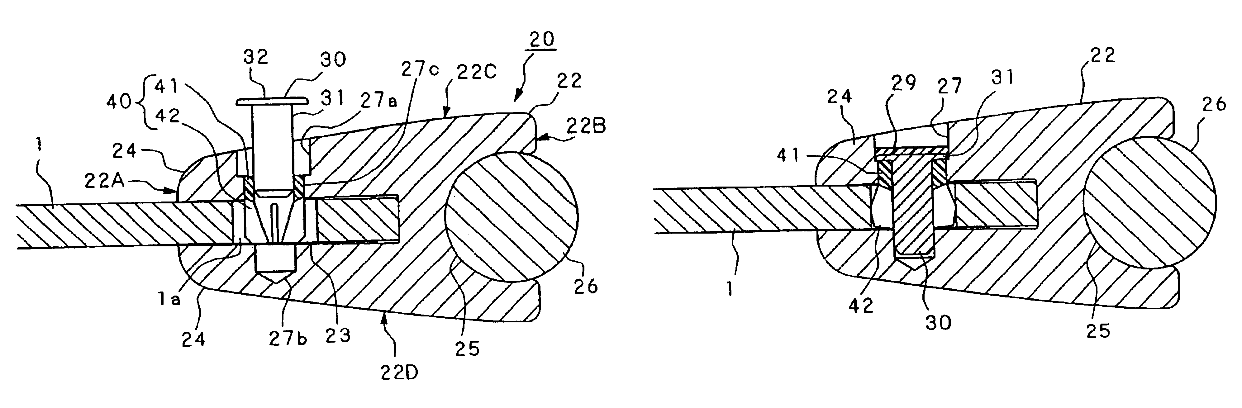
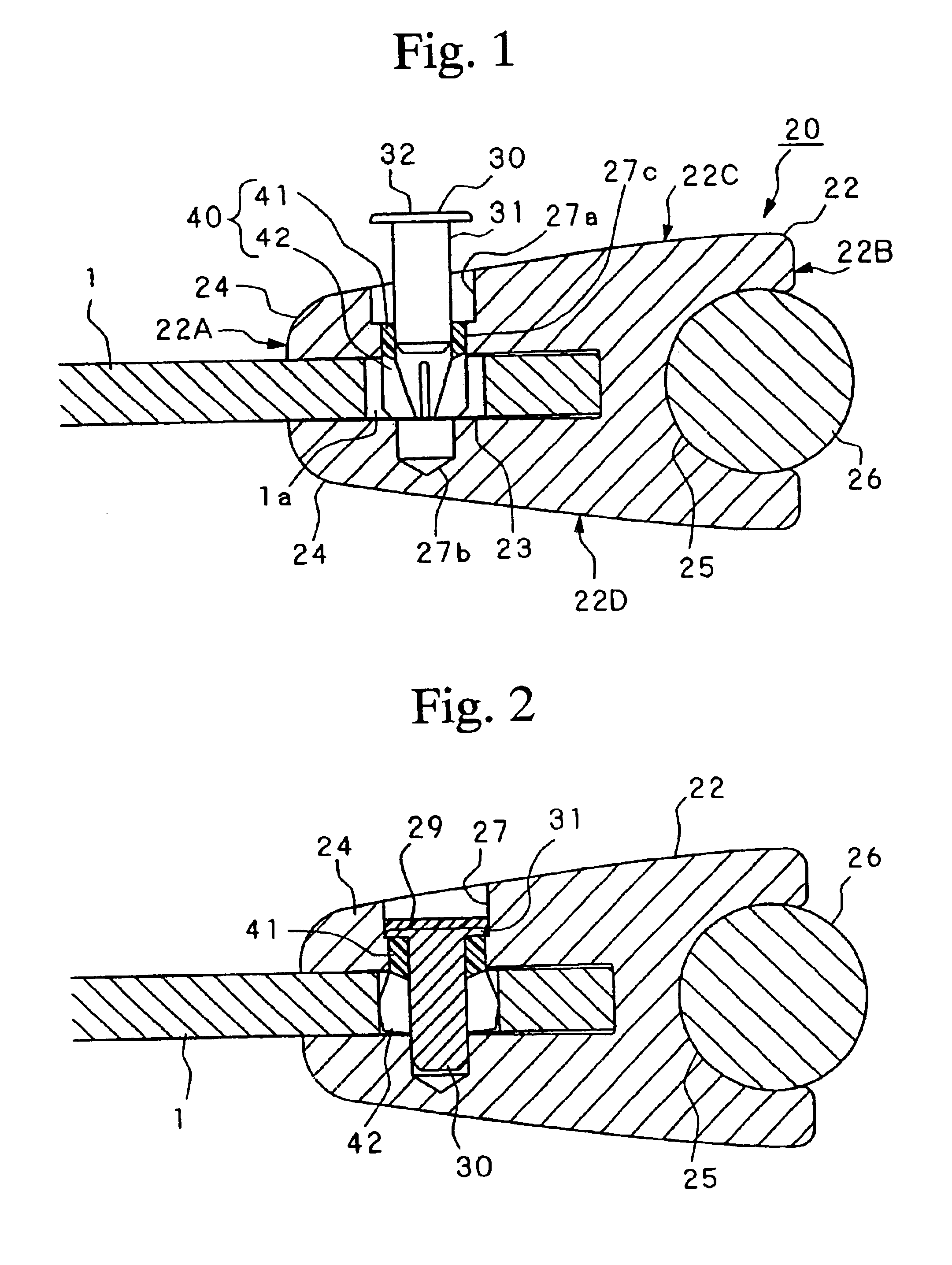
FIGS. 1 and 2 show a first embodiment of the edge insulation member of the present invention, and are figures showing the state in which it is tightly fitted to an electrode plate.

This type of edge insulation member 20 is used, during electrolytic refining, by being fitted to both the edge portions and the lower edge portion of an electrode plate 1 as shown in FIG. 8, or to both the edge portions of the electrode plate as shown in FIG. 9.

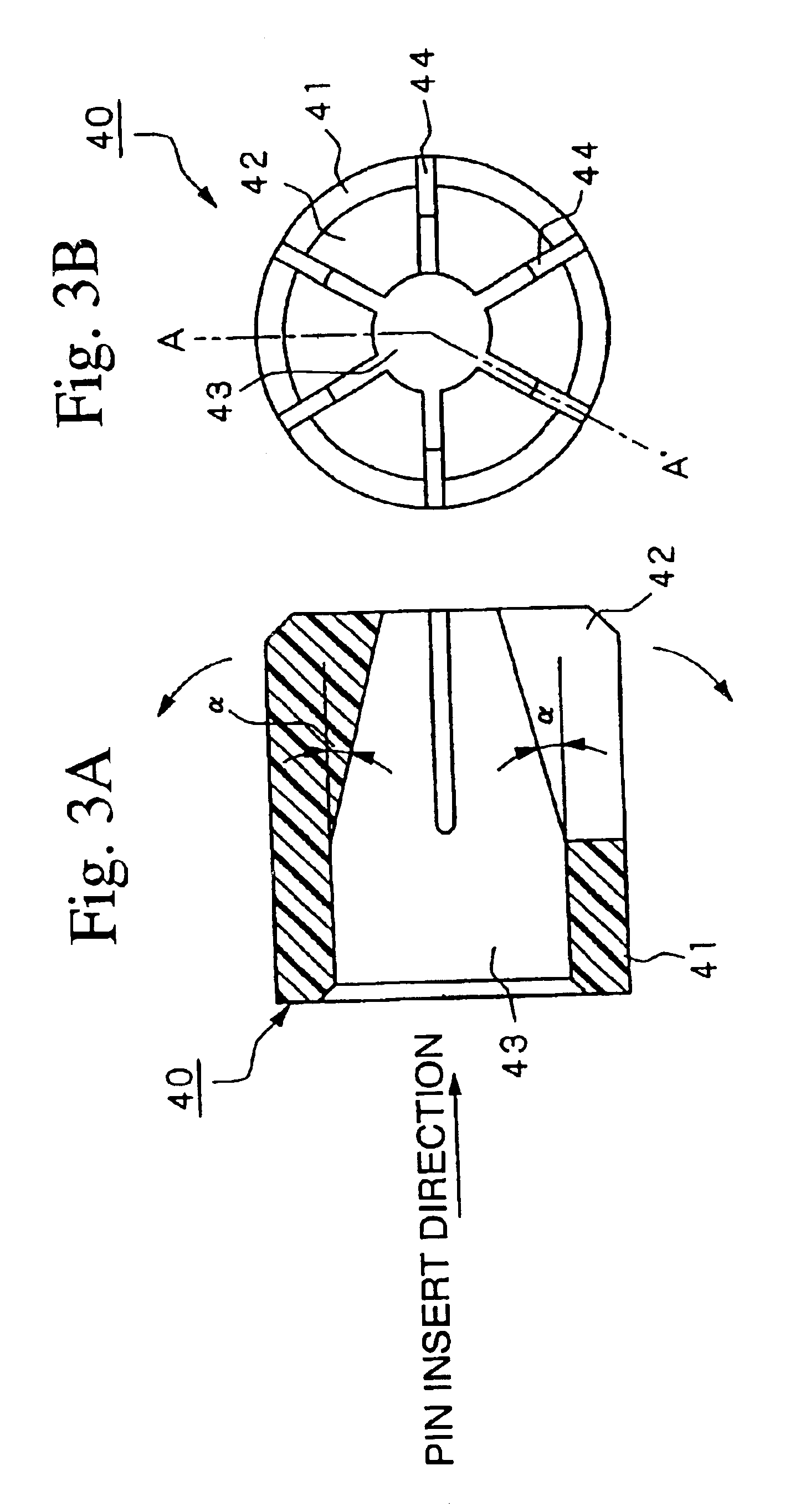
The edge insulation member 20 includes a cylindrically shaped (rod shaped) main body 22, a fitting jig made up from a pin 30 and a stopper 40, and a support rod 26.

A fitting groove 23 and a jaw portion 24 for fitting the electrode plate 1 are formed at a tip portion 22A of the main body 22 so as to extend along the lengthwise direction of the main body 22. The fitting groove 23 is provided for fitting the electrode plate 1 to the main bo...


PUM

PropertyMeasurementUnit
angleaaaaaaaaaa
angle of inclinationaaaaaaaaaa
temperatureaaaaaaaaaa

Abstract

The present invention relates to an edge insulation member for an electrode plate used for electrolytic refinement of metal, and to a fixing method for it. On a tip portion 22A of a main body 22, a fitting groove 23 and a jaw portion 24 for tightly fitting an electrode plate 1 are formed to extend along the lengthwise direction of the main body 22. On a base end portion of the main body 22, an engagement notch 25 for fitting a support rod 26 is formed to extend along the lengthwise direction of the main body 22. A plurality of pin insertion holes 27 are formed on the side surface of the jaw portion 24. Fitting jigs made up from a pin 30 and a stopper 40 is removably fitted in this pin insertion hole 27. The support rod 26 is removably fitted in the engagement notch 25.

Description

TECHNICAL FIELDThe present invention relates to an insulation member which is fitted on the edge portion of an electrode plate which is used during electrolytic refining of copper or the like, to a fixing method and a removal method therefore, and to a fitting jig for an edge insulation member.TECHNICAL BACKGROUNDIn a process for electrolytic refining of a metal such as copper or the like, and in particular in a long duration electrolytic refining and electrolytic sampling process, an electrode plate which is made from a metal such as stainless steel or the like is utilized as the cathode. This cathode is fitted into an electrolytic tank along with an anode which is made of blister copper or the like and electrolytic solution is filled therein; electrolysis is performed so that metal is precipitated and electrodeposited on both sides of the electrode plate. This is ablated so as to obtain the refined product in plate form (in the following, this precipitated and electrodeposited sub...

Claims


Application Information

Patent Timeline
Patent Type & Authority Patents(United States)
IPC IPC(8): C25C7/02C25C7/00C25C1/12
CPCC25C7/02
Inventor TANAKA, HIROSHISHIMIZU, FUMIHIKO
Owner MITSUBISHI MATERIALS CORP
Why Eureka
Try Eureka