
Strainer for a drum

a technology for strainers and drums, applied in the direction of instruments, percussion instruments, instruments, etc., can solve the problems of only being able to operate the pivoting lever of strainers such as these, not being adjustable, and making an unwanted “throw-off” noise of snares

Inactive Publication Date: 2005-01-25
TRICK PERCUSSION PRODS
View PDF16 Cites 42 Cited by
  • Summary
  • Abstract
  • Description
  • Claims
  • Application Information

AI Technical Summary

Benefits of technology

The rotational camming engagement of the strainer, for example between the follower and the helical groove, allows for continuous control of the tension of the snares over at least a portion of the motion of the strainer, so that different sounds can be selected between the snares-on mode and the snares-off mode. Also, the rotational camming engagement of the present invention prevents the unwanted throw-off noise described above because the camming engagement of the actuator and piston is smooth, and does not jerk the snares into, or out of, the snares-on mode.

Problems solved by technology

The pivoting lever of strainers such as these can only be operated so that the snares are either in contact with the drumhead (snares-on mode), or not in contact with the drumhead (snares-off mode), and are not adjustable to different tensions in between.
Further, the strainer tends to be tensioned or released quickly, so that the snares make an unwanted “throw-off” noise against the drumhead, which is very undesirable, particularly for orchestral musicians.
Also, the housings of Nickel's strainers are made from plastic, and have been known to break after only a few months of repeated use in a percussion environment.
Further, none of these disclose a continuously adjustable strainer that prevents the unwanted throw-off noise described above.
However, this strainer does not teach a strainer that is continuously adjustable.
Further, this strainer can still create the undesirable throw-off noise described above, particularly if it is adjusted quickly.

Method used


Image

  • Strainer for a drum
  • Strainer for a drum
  • Strainer for a drum

Examples


Embodiment Construction

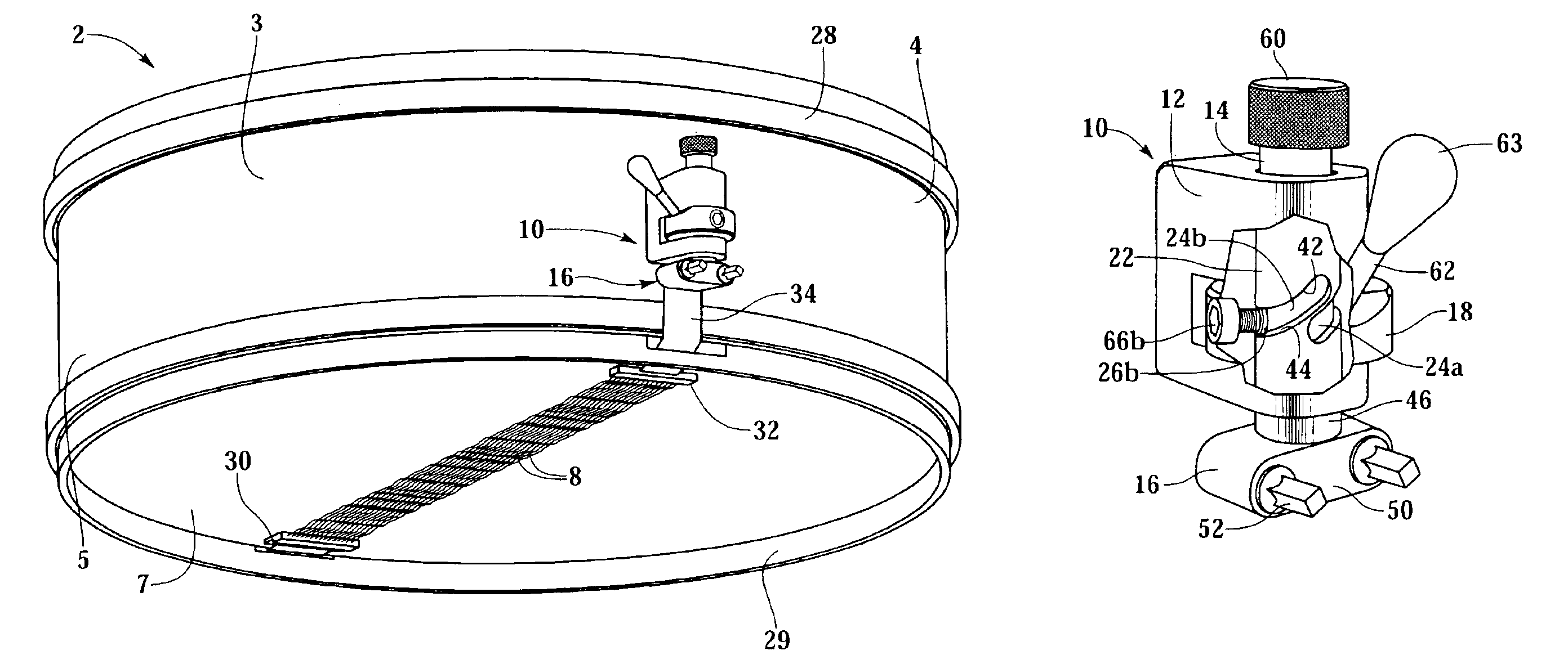
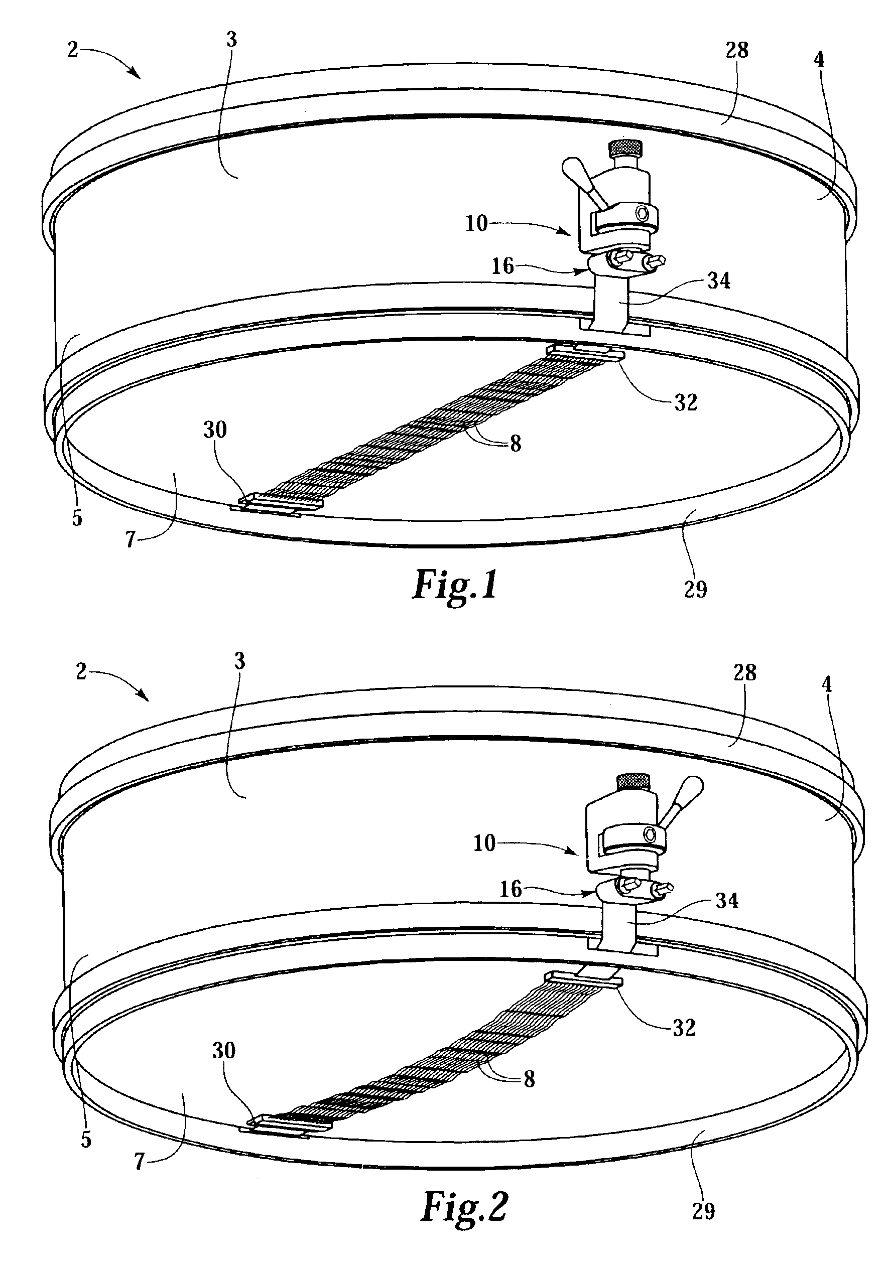
A strainer 10, sometimes called a “throw-off” mechanism, for use on a snare drum 2 is shown in FIGS. 1 and 2. Snare drum 2 includes a shell 3 having an upper end 4 and a lower end 5, with an upper drumhead (not shown) mounted on upper end 4 and a lower drumhead 7 mounted on lower end 5. A plurality of snares 8 are mounted to snare drum 2 so that they are proximate and generally parallel to lower drumhead 7.

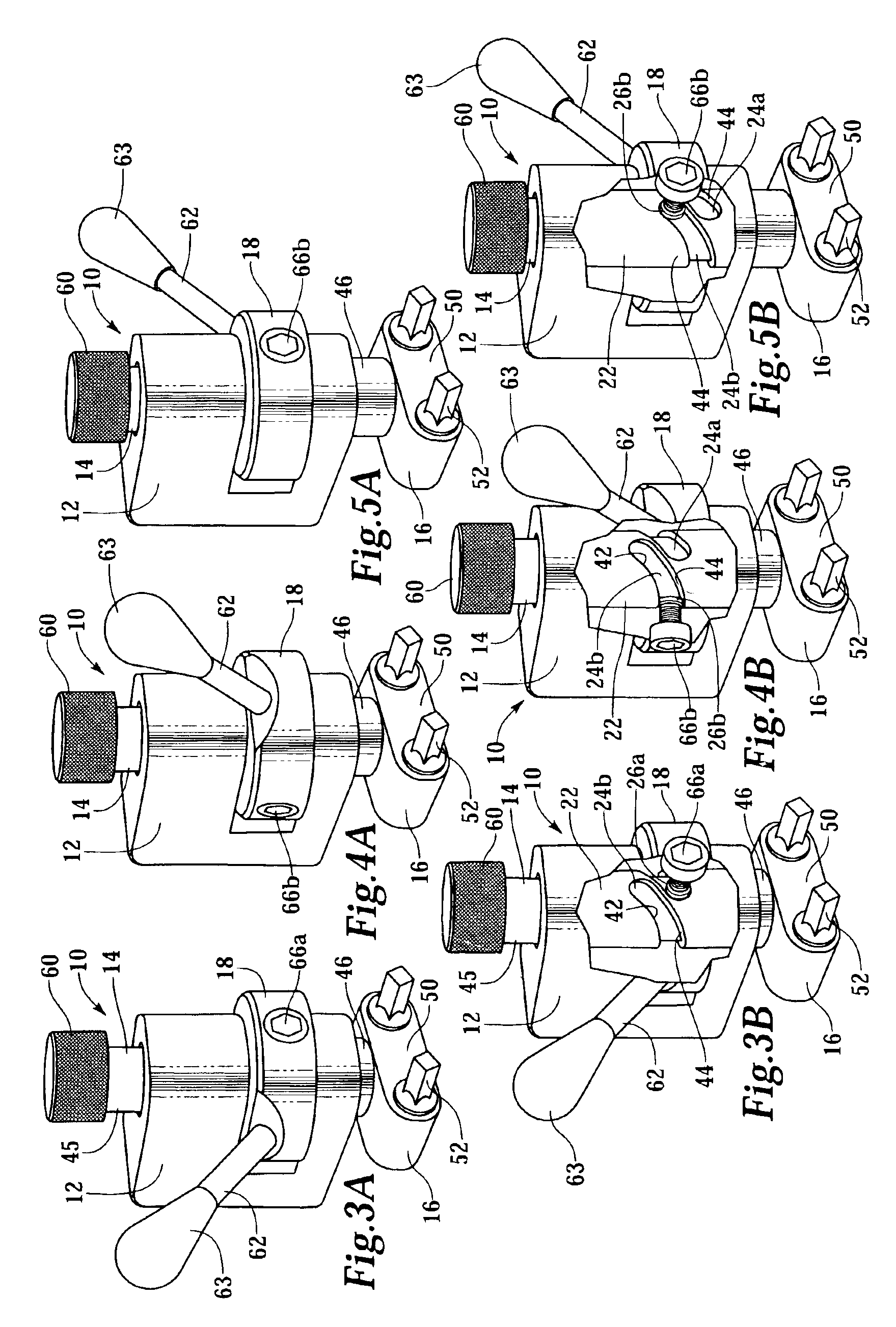
Snares 8 are movable between a tensioned, or snares-on mode, as shown in FIG. 1, and an untensioned, or snares-off mode, as in FIG. 2. Snares 8 are tensioned and untensioned by strainer 10 of the present invention. The novel strainer 10 includes a piston 14 mountable to shell 3 of drum 2 so that piston 14 can reciprocate, and an actuator 18 cammingly engageable with piston 14. Piston 14 has an axis of reciprocation 20 and a surface 22 curved around an axis 21 that is generally parallel to axis of reciprocation 20. Snares 8 are operatively connectable to piston 14, such as by snare...


PUM


Abstract

A snare drum strainer mountable to the shell of a drum comprises a piston and an actuator. The piston has an axis and a surface curved about an axis generally parallel to the piston axis, and the piston is operatively connected to snares. The actuator and the curved surface rotate one with respect to the other about an axis generally parallel to the piston axis to reciprocate the piston and to tension and untension the snares. In another embodiment, the piston includes a generally cylindrical surface with a generally helical groove, the piston is operatively connected to snares, and the actuator includes a follower insertable into the generally helical groove. The follower and the generally cylindrical surface rotate one with respect to the other to reciprocate the piston and tension and untension the snares.

Description

BACKGROUND OF THE INVENTION1. Field of the InventionThe present invention is directed to a strainer for use with a drum, in particular to an adjustable strainer for use with a snare drum.2. Description of the Related ArtSnare drums typically include a plurality of wires, or snares, which contact a bottom drumhead of the snare drum so that the snares are vibrated by the vibration of the bottom drumhead when the snare drum is played. A strainer is typically used to tension the snares in order to change the tone produced by the drum by changing the position of the snares so that they are either in contact or not in contact with the drumhead.U.S. Pat. Nos. 5,557,053 and 6,093,877 to Nickel are examples of conventional strainers for snares of a snare drum. These strainers use a lever directly connected to a piston, wherein the lever pivots about an axis generally perpendicular to the piston, so that when the lever is pivoted from one position to another, the piston drops and the tension ...

Claims


Application Information

Patent Timeline
Patent Type & Authority Patents(United States)
IPC IPC(8): G10D13/02G10D13/00
CPCG10D13/025G10D13/02G10D13/18
Inventor DORFMAN, MICHAELSZWAYA, ROBERTSZWAYA, GEORGE
Owner TRICK PERCUSSION PRODS
Learn More