Intermittent operating type pointing device

a pointing device and intermittent operation technology, applied in the direction of static indicating devices, counting objects on conveyors, instruments, etc., can solve the problems of large power consumption and short battery life, and achieve the effect of high resolution and easy prevention of false detection

Inactive Publication Date: 2005-01-25
ALPS ALPINE CO LTD
View PDF4 Cites 5 Cited by
  • Summary
  • Abstract
  • Description
  • Claims
  • Application Information

AI Technical Summary

Benefits of technology

As mentioned above, the amount of change in the driving period to be extended is set to be small. Consequently, even when the moving speed is gradually reduced, high resolution can be maintained, thus easily preventing false detection.

Problems solved by technology

In the foregoing conventional input devices, generally, the light sources continuously emit light, resulting in large power consumption.
For example, in the mouse type input device using a battery as a power supply or an input device mounted on a notebook-sized personal computer using a battery as a power supply, battery life is short.

Method used


Image

  • Intermittent operating type pointing device
  • Intermittent operating type pointing device
  • Intermittent operating type pointing device

Examples


first embodiment

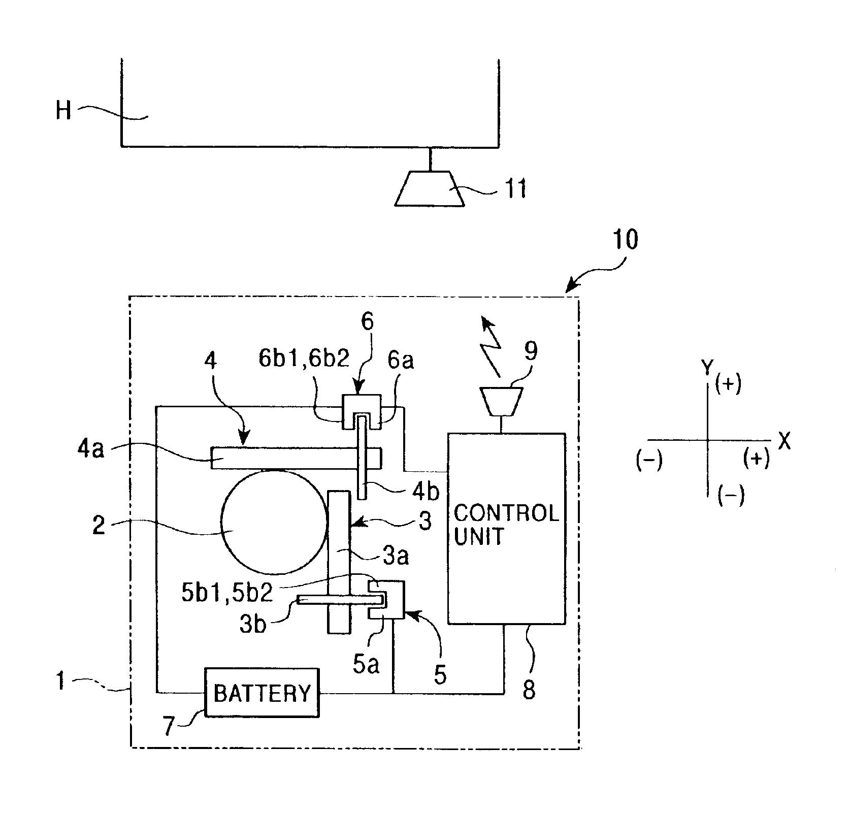
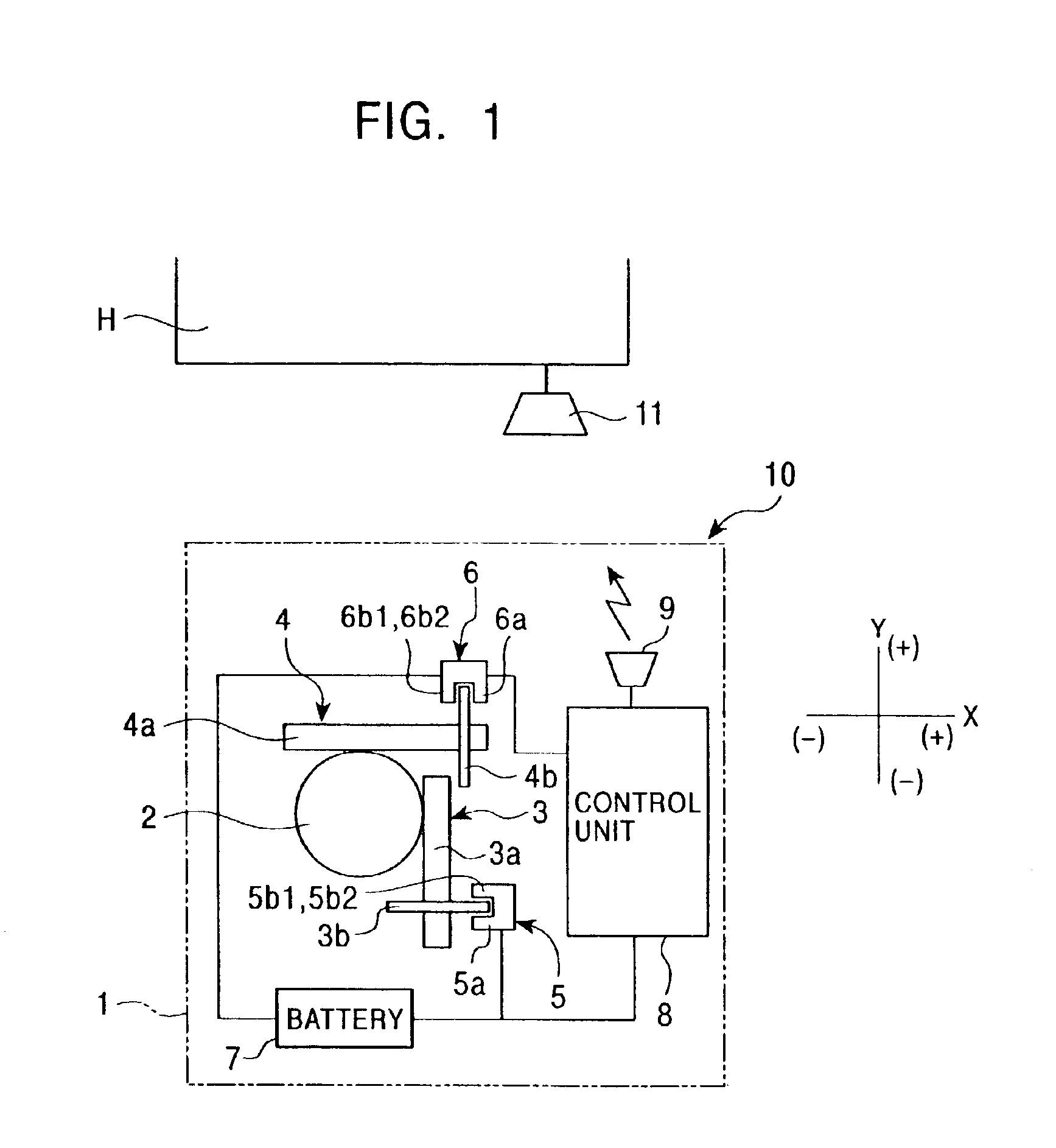
FIG. 1 shows a functional block diagram of the internal configuration of an input device according to the present embodiment.

Referring to FIG. 1, an input device 10 is a mouse type pointing device. The input device 10 has a case 1 made of a synthetic resin. The size of the case 1 is set so that the user can control the input device 10 while grasping the case 1. A ball 2 is received in the case 1. The ball 2 is rotatably held in the case 1 so that a part of the surface of the ball 2 is exposed from the bottom of the case 1. When the ball 2 exposed from the case 1 is applied to a pad and is then moved, the ball 2 can be rotated.

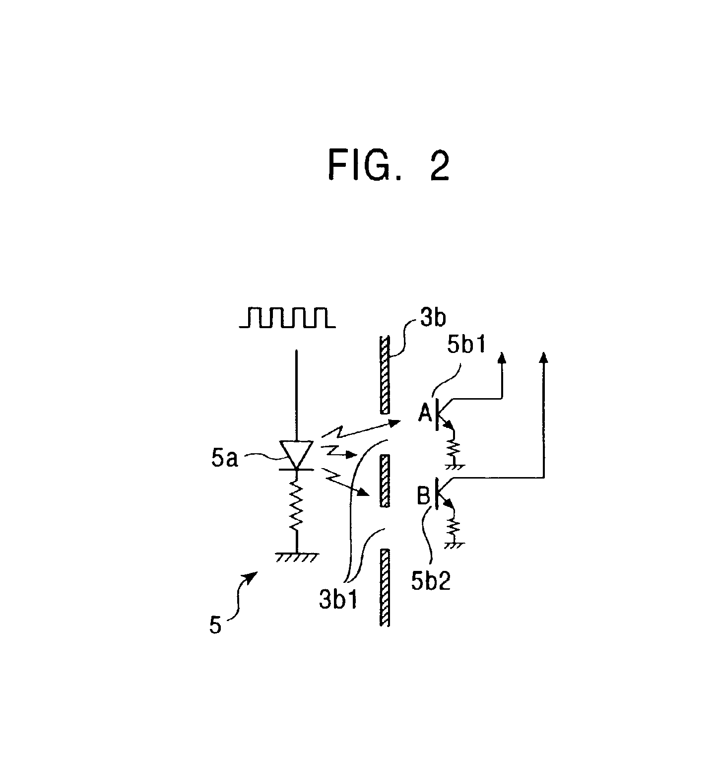
In the case 1, an X-axis encoder 3 and a Y-axis encoder 4, each of which is in contact with the ball 2 and is rotated thereby, are arranged perpendicularly to each other. The X-axis encoder 3 has a roller-shaped rotary shaft 3a disposed along the Y-axial direction (Y-direction). An X-axis rotary member 3b is formed at a portion close to one end of the rotary sh...

second embodiment

FIG. 6 is a functional block diagram of an input device according to the present invention.

An input device 20 is a mouse type pointing device having no ball. When the input device 20 is moved on the surface of a pad or a table serving as a reference element, the input device 20 detects the movement of an image of the reference element to recognize the amount of movement and the moving speed of the input device 20 in the X-direction and the amount of movement and the moving speed thereof in the Y-direction.

The input device 20 has a case 21. The case 21 includes a detector 22 such as a CCD camera which can capture the image of the reference element in a predetermined range and a photoemitter 23 such as a light emitting diode (LED) or the like for irradiating the reference element in order to easily capture the image thereof.

The case 21 also includes a control unit 25 which has an image processing function. The detector 22 comprises a CCD and detects the variations of light and shade s...


PUM


Abstract

In detecting units for detecting the rotating operation of a ball, respective photoemitters serving as light sources are intermittently driven to emit light and respective photodetectors receive the light. A control unit recognizes a moving speed in the X-axial direction and that in the Y-axial direction from detection signals obtained by the detecting units. In the control operation of the control unit, when an increase in operating speed is detected, a light emitting period of each of the photoemitters is reduced. When a decrease in operating speed is detected, the light emitting period of each photoemitter is extended.

Description

BACKGROUND OF THE INVENTION1. Field of the InventionThe present invention relates to a mouse type input device which can detect the amount of movement due to an operating physical force, and more particularly to an input device which can reduce power consumption.2. Description of the Related ArtInput devices for detecting the amount of movement thereof due to an operating physical force include the following types. Each of some type input devices has a ball-shaped or roller-shaped control element. The control element is rotated by a finger and the amount of rotation thereof is detected and is then transmitted to a host computer. Each of mouse type input devices includes a case. The case is moved while being held by a hand and the amount of movement thereof is detected.These input devices have means for detecting the amount of movement. These detecting means have the similar structures. For example, according to the mouse type input device, a ball is rotatably held in the case. When ...

Claims


Application Information

Patent Timeline
Patent Type & Authority Patents(United States)
IPC IPC(8): G06F3/033G01B11/00G06F3/0354G06F3/038
CPCG06F3/0383G06F3/03549
Inventor SHIGA, SADAKAZU
Owner ALPS ALPINE CO LTD
Why Eureka
Try Eureka