Pumping circuit for outputting program voltage and program verify voltage of different levels

Inactive Publication Date: 2005-01-25
SK HYNIX INC
View PDF4 Cites 16 Cited by
  • Summary
  • Abstract
  • Description
  • Claims
  • Application Information

AI Technical Summary

Benefits of technology

Meanwhile, the pumping circuit according to the present invention is characterized in that it comprises first and second clock generators for generating first and second clock signals having opposite phases, a third clock generator for logically combining the first clock signal and an inverted signal of a program verify signal to generate a third clock signal, a fourth clock generator for logically combining the second clock signal and the inverted signal of the program verify signal to generate a fourth clock signal, a plurality of diodes connected between respective nodes between an input node and an output node, for transferring the voltage of a previous node to a next node, a plurality of capacitors connected between the plurality of the diodes which are connect

Problems solved by technology

Therefore, as the pumping voltage must be regulated as the program verify level using the pumping circuit for generating the program voltage, many ripples may occur and the active current is also increased.
The ripples in this program verify operation m

Method used


Image

  • Pumping circuit for outputting program voltage and program verify voltage of different levels
  • Pumping circuit for outputting program voltage and program verify voltage of different levels
  • Pumping circuit for outputting program voltage and program verify voltage of different levels

Examples


Embodiment Construction

The present invention will be described in detail by way of a preferred embodiment with reference to accompanying drawings, in which like reference numerals are used to identify the same or similar parts.

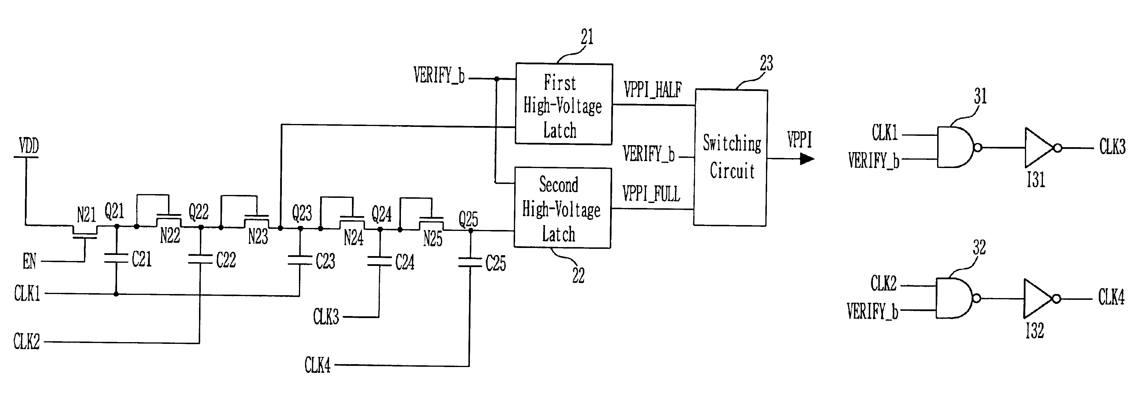
FIG. 3 shows a pumping circuit according to a preferred embodiment of the present invention. The construction of the pumping circuit according to the present invention will be below described by reference to FIG. 3.

A first NMOS transistor N21 driven by an enable signal (EN) is connected between the power supply terminal VDD and a first node Q21. A second NMOS transistor N12 is diode-connected between the first node Q21 and a second node Q22. A third NMOS transistor N23 is diode-connected between the second node Q22 and a third node Q23. A fourth NMOS transistor N24 is diode-connected between the third node Q23 and a fourth node Q24. A fifth NMOS transistor N25 is diode-connected between the fourth node Q24 and a fifth node Q25. Also, first and third capacitors C21 and C23 charged ac...


PUM


Abstract

The present invention relates to a pumping circuit. The pumping circuit comprises a first pumping block for pumping an input voltage, a first latch for latching the output of the first pumping block, a second pumping block for pumping the output of the first pumping block according to a control signal, a second latch for latching the output of the second pumping block, and a switching circuit for selectively outputting the outputs of the first and second latches according to the control signal. Thus, a program voltage and a program verify voltage of different levels are pumped. The ripple and active current can be reduced and the program efficiency can be increased.

Description

BACKGROUND OF THE INVENTION1. Field of the InventionThe invention relates generally to a pumping circuit, and more particularly to, a pumping circuit wherein a program voltage and a program verify voltage of different levels are pumped using a program verify signal, thus reducing ripples and active current.2. Description of the Prior ArtIn the flash memory device, program, erase and read operations are performed according to the voltage applied to the word line of a selected cell, drain / source, and the substrate. In order to perform the program operation of the flash memory cell, it is required that a pumping voltage of about 9V higher a little than the power supply voltage be generated using a pumping circuit and a regulation circuit and the generated voltage be then applied to the word line of the selected cell. .FIG. 1A shows a common pumping circuit that is used to program the flash memory cell. The construction of the pumping circuit in FIG. 1A will be below described.A first N...

Claims


Application Information

Patent Timeline
IPC IPC(8): H02M3/04H02M3/07G11C16/12
CPCH02M3/073G11C16/12
Inventor KIM, YOUNG JOO
Owner SK HYNIX INC
Why Eureka
Try Eureka