Waveguide group branching filter

a filter and waveguide technology, applied in the direction of waveguides, electrical devices, coupling devices, etc., can solve the problems of reducing manufacturing costs, difficult miniaturization, and large bulky circuit structure of the entire circuit, and achieve excellent reflection and polarized wave isolation characteristics

Inactive Publication Date: 2005-01-25
MITSUBISHI ELECTRIC CORP
View PDF23 Cites 8 Cited by
  • Summary
  • Abstract
  • Description
  • Claims
  • Application Information

AI Technical Summary

Benefits of technology

This structure permits realization of a high-performance waveguide group branching filter of highly excellent reflection and polarized waves isolation characteristics and, at the same time, facilitates its miniaturization and reduction of its manufacturing cost.
This structure permits realization of a high-performance waveguide group branching filter of excellent reflection and polarized waves isolation characteristics.

Problems solved by technology

The conventional waveguide group branching filter has such a construction as described above, and hence it requires a combiner circuit (not shown) for combining radio waves of the same polarization separated between the two opposed waveguide low-pass filters 63b and a combiner circuit (not shown) for combining radio waves of the same polarization similarly separated between the two waveguide low-pass filters 63b; accordingly, the entire circuit structure is very bulky and is difficult of miniaturization.
Moreover, because of its cubic structure, the integral formation of respective components is not easy, giving arise to the problem of difficulty in the reduction of manufacturing costs.

Method used


Image

  • Waveguide group branching filter
  • Waveguide group branching filter
  • Waveguide group branching filter

Examples


embodiment 1

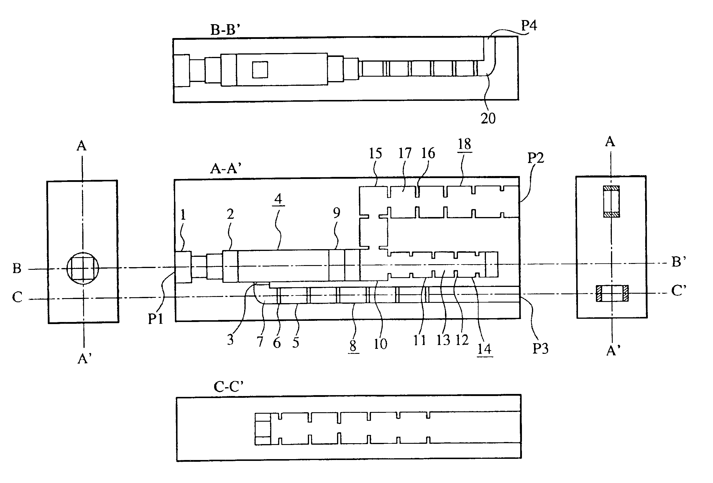
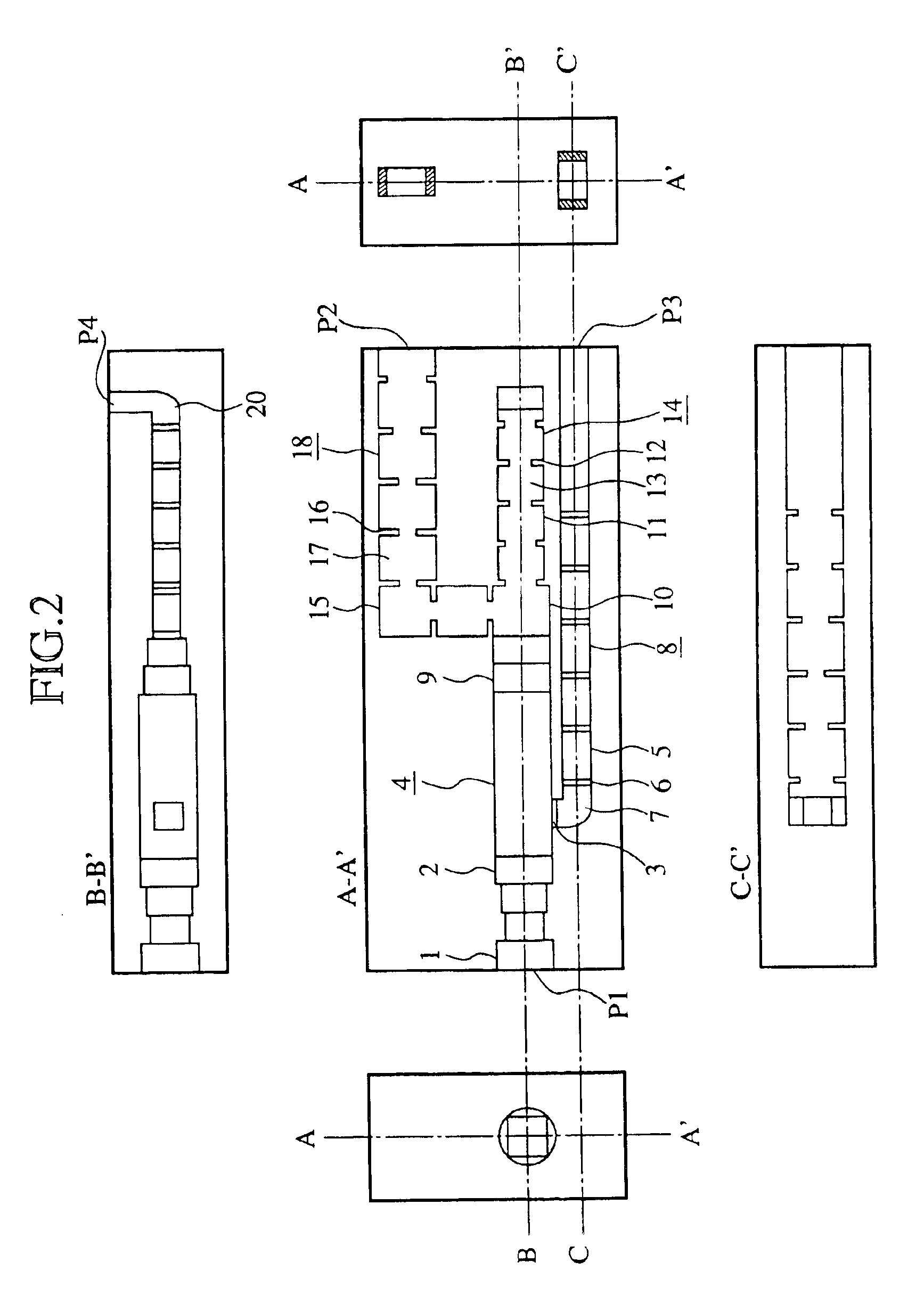
FIG. 2 is a diagrammatic showing of a waveguide group branching filter according to Embodiment 1 of the present invention. In FIG. 2, reference numeral 1 denotes a circular-to-square waveguide multistage transformer; 2 denotes a square waveguide connected to one end of the circular-to-square waveguide multistage transformer 1; 3 denotes a coupling hole formed through one sidewall of the square waveguide 2; 4 denotes a branch waveguide polarizer / branching filter formed by the square waveguide 2 and the coupling hole 3; 5 denotes a rectangular waveguide connected to the branching end of the branch waveguide polarizer / branching filter and having an E-plane bend; 6 denotes n (where n is an integer equal to or greater than 1) iris-type coupling holes provided in the rectangular waveguide 5; 7 denotes n rectangular cavity resonators separated by the coupling hole 3 and the n coupling holes 6 in the rectangular waveguide 5; and 8 denotes generally a waveguide band-pass filter (a first wave...

embodiment 2

FIG. 3 is a diagrammatic showing of a waveguide group branching filter according to Embodiment 2 of the present invention. In FIG. 3, reference numeral 21 denotes two coupling holes formed through one side wall of the square waveguide 2; and 22 denotes generally a branch waveguide polarizer / branching filter formed by the square waveguide 2 and the two coupling holes 21.

While Embodiment 1 is provided, as depicted in FIG. 2, with the branch waveguide polarizer / branching filter 4 composed of the square waveguide 2 and the single coupling hole 3, Embodiment 2 is provided, as depicted in FIG. 3, with the branch waveguide polarizer / branching filter 22 in place of the branch waveguide polarizer / branching filter 4 shown in FIG. 2; however, this embodiment is identical in construction with Embodiment 1 of FIG. 2 except the above.

The radio waves V1 and V2 incident from the input port P1 do not couple with the two coupling holes 21 in the branch waveguide polarizer / branching filter 22 having t...

embodiment 3

FIG. 4 is a diagrammatic showing of a waveguide group branching filter according to Embodiment 3 of the present invention. In FIG. 4, reference numeral 23 denotes a thin metal sheet inserted in the square waveguide 2; and 24 denotes generally a branch waveguide polarizer / branching filter made up of the square waveguide 2, the single coupling hole 3 and the thin metal sheet 23.

While Embodiment 1 is provided, as depicted in FIG. 2, with the branch waveguide polarizer / branching filter 4 composed of the square waveguide 2 and the single coupling hole 3, Embodiment 3 is provided, as depicted in FIG. 4, with the branch waveguide polarizer / branching filter 24 in place of the branch waveguide polarizer / branching filter 4 shown in FIG. 2; however, this embodiment is identical in construction with Embodiment 1 of FIG. 2 except the above.

The radio wave H1 incident from the input port P1 forms a standing wave due to the cutoff effect by the thin metal sheet 23, then couples with the fundamental...


PUM


Abstract

The waveguide group branching filter according to the present invention is formed by boring out of two metal blocks constituent circuits including a circular-to-square waveguide multistage transformer 1, the branch waveguide polarizer / branching filter 4, a rectangular waveguide multistage transform 9, the rectangular waveguide H-plane T-branch circuit 10, and waveguide band-pass filters 8, 14 and 18; radio waves V1 and H1, which have their polarization planes vertical and horizontal, respectively, to the branching plane of the branch waveguide polarizer / branching filter 4 in a certain frequency band f1, and a radio wave V2 of the same polarization plane as that of the radio wave V1 in a frequency band f2 higher than the frequency band f1 are incident to an input port P1, and the radio wave V1 is emitted from an output port P2, the radio wave H1 from an output port P3 and the radio wave V2 from an output port P4.

Description

TECHNICAL FIELDThe present invention relates to a waveguide group branching filter that is used mainly in VHF, UHF, microwave and millimeter wave bands.TECHNICAL FIELDFIG. 1 is a perspective view showing a conventional waveguide group branching filter set forth, for example, in J. Bornemann, U. Rosenberg, “Waveguide Components for Antenna Feed Systems: Theory and CAD,” ARTECH HOUSE INC., pp. 413-418, 1993. In FIG. 1, reference numeral 61 denotes a square main waveguide; 62a denotes coupling holes of the same shape formed through two opposed side walls of the square main waveguide 61 in symmetrical relation to each other; and 62b denotes coupling holes of the same shape formed symmetrically through two other opposed side walls of the square main waveguide 61 than those through which the coupling holes 62a are formed.Furthermore, in FIG. 1, reference numeral 63a denotes two waveguide low-pass filters that branch off via the coupling holes 62a from longitudinal axis of the square main ...

Claims


Application Information

Patent Timeline
IPC IPC(8): H01P1/213H01P1/20H01P1/161H01P1/17H01P1/207H01P1/208H01P1/211
CPCH01P1/2138
Inventor YONEDA, NAOFUMIMIYAZAKI, MORIYASUYAMAGATA, KOUSAKU
Owner MITSUBISHI ELECTRIC CORP
Why Eureka
Try Eureka