Liquid crystal display with reflecting polarizer

a liquid crystal display and polarizer technology, applied in the field of display information devices, can solve the problems of small viewing angle, low contrast, and low brightness of traditional displays, and achieve the effects of increasing display brightness, increasing contrast and richness, and increasing viewing angl

Inactive Publication Date: 2005-01-25
NITTO DENKO CORP
View PDF20 Cites 13 Cited by
  • Summary
  • Abstract
  • Description
  • Claims
  • Application Information

AI Technical Summary

Benefits of technology

Accordingly, one object of the present invention is to provide a display that has increased display brightness, spectrally clean color images, and is capable of creating white, black and color components in color image to increase the contrast and richness of the image, and has increased viewing angle of the display.

Problems solved by technology

The main drawback of traditional displays is the small viewing angle since only the light flow propagating towards the front surface of the multilayer LC display within the limits of a confined cone angle efficiently governs the multilayer design of the LC display.
The traditional displays also have relatively low brightness, low contrast and high power consumption due to the large number of absorbing layers.
Using absorbing filters may cause additional light losses in the device and as a consequence increase energy consumption.
One of the drawbacks of using such polarizers for color display is that they reflect light in a wide spectral range which leads to smeared colors.

Method used


Image

  • Liquid crystal display with reflecting polarizer
  • Liquid crystal display with reflecting polarizer
  • Liquid crystal display with reflecting polarizer

Examples


Embodiment Construction

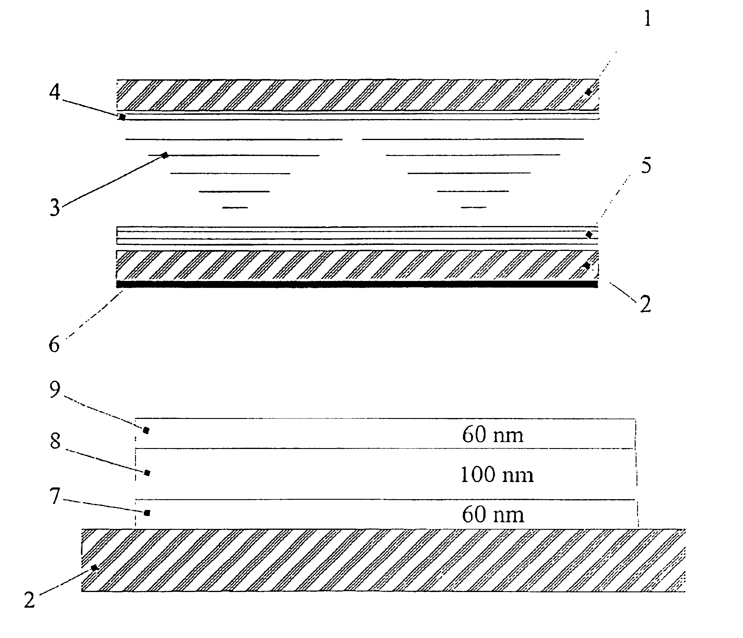
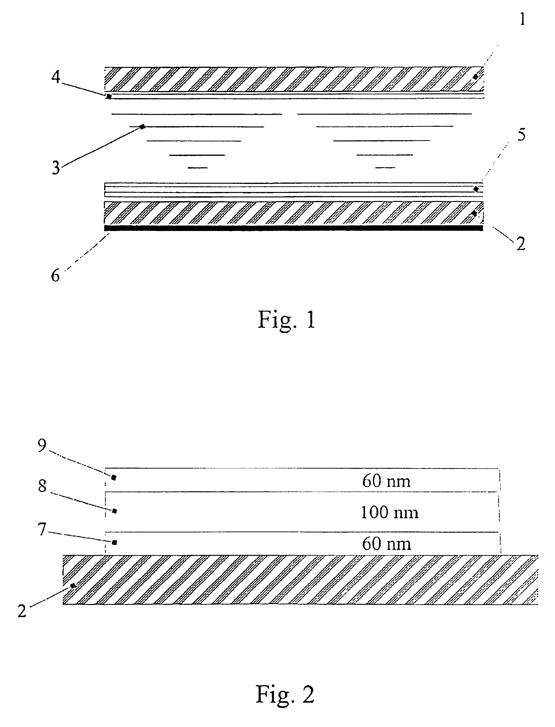
The LC display of the present invention shown in FIG. 1 includes front and rear panels 1 and 2 with functional layers such as electrodes, planarization layer, adhesion layer and a layer of liquid crystal 3 disposed between the front and rear panels. On the inner side of the front panel 1 is a thin crystalline film 4 functioning as a dichroic polarizer. The crystalline film 4 may be formed according to the method described below from LLC containing 12.5% mixture of dyes (Vat Blue 4; bis-benzimidazole-[2,1-a:1′2′b′]anthra[2,1,9-def:6,5,10-d′e′f′]diisoquinoline-6,9-dion; Vat Red 15 in the ratio 5.2:2:1). The LLC is transferred into an insoluble from after being treated with Barium ions. The thickness of the crystalline film 4 is about 100 nm. Since the crystalline film 4 is a highly ordered anisotropic film, it may simultaneously work as an alignment layer for the liquid crystal.

On the internal surface of the rear panel 2 is provided a reflecting polarizer 5 having a multilayer structu...


PUM

PropertyMeasurementUnit
wavelengthaaaaaaaaaa

Abstract

A liquid crystal display is provided which comprises front and rear panels, and electrodes, polarizers and a layer of liquid crystal disposed between the front and rear panels. The polarizer on the rear panel is preferably a reflecting type in at least one region of the spectrum and contains at least one element in the form of a multilayer structure. The multilayer structure contains at least two anisotropic layers separated by at least one intermediate layer which is optically transparent in the desired spectral region. The ratio of refraction indices and thickness of the layers in the multilayer structure is chosen such to provide an extremum for the ratio of the transmitted and reflected polarized light in the spectral region.

Description

FIELD OF THE INVENTIONThe present invention relates generally to devices of displaying information, and in particular to liquid crystal displays (LCDs).BACKGROUND OF THE INVENTIONThere are known displays embodied in flat cells. A cell is usually formed by two parallel glass plates, on the inner sides of which are electrodes made from optically transparent conducting materials, and alignment layers. After assembly of the cell, the cell is filled with a liquid crystal material which forms a layer having thickness ranging from 5 to 20 μm. The liquid crystal material is an active medium that changes its optical properties such as angle of rotation of polarization plane under the influence of an electric field. Variations of optical properties are viewed in the crossed polarizers, which are usually glued on the external surfaces of the cell. The areas of the display where electrodes are not electrically charged transmit light and look bright, while the areas under voltage look dark (L. K...

Claims


Application Information

Patent Timeline
Patent Type & Authority Patents(United States)
IPC IPC(8): C09K19/60G02F1/1335G02B5/30G02F1/13
CPCC09K19/60G02F1/133536G02B5/305G02F1/1335
Inventor LAZAREV, PAVEL I.PAUKSHTO, MICHAEL V.YAO-DONG, MA
Owner NITTO DENKO CORP
Why Eureka
Try Eureka