Liquid-crystal display and a lighting apparatus

a liquid crystal display and lighting apparatus technology, applied in lighting and heating apparatus, identification means, instruments, etc., can solve the problems of lowering luminance and attending with loss, and achieve the effect of increasing the intensity of light fed and high intensity

Inactive Publication Date: 2005-01-25
SHARP KK
View PDF29 Cites 155 Cited by
  • Summary
  • Abstract
  • Description
  • Claims
  • Application Information

AI Technical Summary

Benefits of technology

It is therefore an object of the present invention to provide a liquid-crystal display of PDLC or a liquid-crystal display using a polarizer in combination with a liquid crystal in which luminance is improved and a lighting apparatus suitable for use with a liquid-crystal display.
In these reflective liquid-crystal displays, the p-polarized light of the polarized light emitted form the light guiding plate to the polarizer can be selectively emitted from the polarizer. Since the p-polarized light has high intensity, it is possible to increase the intensity of light fed from the polarizer to the liquid-crystal panel.

Problems solved by technology

However, the panel of this type is attended with a problem of loss in a process of scattering of light.
On the other hand, the panel using a polarizer in combination with a liquid crystal is attended with a problem that luminance is lowered by the presence of the polarizer.

Method used


Image

  • Liquid-crystal display and a lighting apparatus
  • Liquid-crystal display and a lighting apparatus
  • Liquid-crystal display and a lighting apparatus

Examples


fifth embodiment

Referring now to FIGS. 24 and 25, description will be given of the scanning backlight in the

FIG. 24 shows structure of the scanning backlight in a cross-sectional view. FIG. 25 shows in a plan view a general configuration of a scanning backlight including a scanning line driving circuit for the scanning of the scanning backlight.

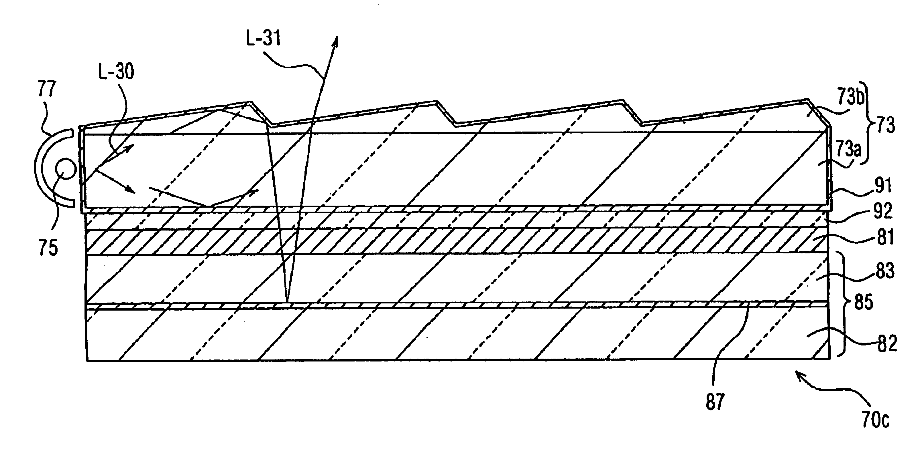
As shown in FIG. 24, a scanning backlight SB1 includes a substrate 311, a common electrode 315 formed on the substrate 311, a fluorine-based liquid-crystal layer 309a formed on the electrode 315, a scanning liquid-crystal layer EM formed on the layer 309a, the layer EM including a surface having projections and depressions; and a transparent polyimide layer 308 formed on the layer EM. A transparent substrate 301 is arranged to oppose the substrate 311, and many transparent electrodes 303 are formed on a lower surface of the transparent substrate 301. The transparent electrode 303 is a band-shaped electrode extending, for example, from the upper-surface side ...


PUM

PropertyMeasurementUnit
refractive indexaaaaaaaaaa
alignment angleaaaaaaaaaa

Abstract

A liquid-crystal display includes a reflective liquid-crystal panel, a light guiding plate disposed on the reflective liquid-crystal panel, a polarizer arranged between a liquid-crystal layer of the reflective liquid-crystal panel and the light guiding plate, and a light source disposed on a side surface of the light guiding plate. Light emitted from the light source propagates through the light guiding plate and has a primary direction. A smaller one of two angles between a projection of the primary direction onto the reflective liquid-crystal panel and an absorption axis of the light guiding plate is at least 50°. This resultantly improves performance of the liquid-crystal display.

Description

This application is based on Japanese Patent Application 2001-034713, filed on February 9, all the content of which is incorporated in this application by reference.BACKGROUND OF THE INVENTION1. Field of the InventionThe present invention relates to a liquid-crystal display (LCD), and in particular, to a reflective liquid-crystal display.2. Description of the Related ArtRecent development of notebook-sized personal computers, portable telephones, and the like has spurred research and development of a reflective liquid-crystal display. The liquid-crystal display of this type does not require any subordinate lighting apparatus when used, for example, outdoors. Additionally, the display is quite suitably used with complementary metal-oxide semiconductors (CMOS). Therefore, power consumption of the display can be easily reduced. The reflective liquid-crystal display is highly promising in consideration of the protection of the environments of the earth.In general, a lightguide or guidin...

Claims


Application Information

Patent Timeline
Patent Type & Authority Patents(United States)
IPC IPC(8): G02F1/1335G02F1/13F21V8/00F21Y103/00G02F1/13357G09F9/00
CPCG02F1/133615G02F1/1335
Inventor GOTOH, TAKESHIHAMADA, TETSUYAKOBAYASHI, TETSUYAHAYASHI, KEIJISUZUKI, TOSHIHIRO
Owner SHARP KK
Why Eureka
Try Eureka