
Self-supporting cables and an apparatus and methods for making the same

a self-supporting cable and cable technology, applied in the field of cables and cables, can solve the problems of elongation of the core section, attenuation losses, and high tension of self-supporting cables

Inactive Publication Date: 2005-01-25
CORNING OPTICAL COMM LLC
View PDF31 Cites 48 Cited by
  • Summary
  • Abstract
  • Description
  • Claims
  • Application Information

AI Technical Summary

Benefits of technology

The present invention relates to cables, particularly fiber optic cables, that can include at least one optical fiber. These cables can be self-supporting, meaning they have a messenger wire and a core section with no excess length relative to the messenger wire. The invention provides methods for making these cables and also provides cables that have an elongated core section, which can be beneficial for high tension applications. The extruder cross-head used to manufacture these cables can be designed to form continuous or intermittent webs for connecting cable sections. The cables can be used in various applications, such as for transmitting data or power. The invention also provides a solution for preventing attenuation and mechanical reliability issues in the optical fibers.

Problems solved by technology

When installed in a self-supporting application, self-supporting cables may experience a high degree of tension.
As tension acts on the messenger wire, however, the messenger wire tends to elongate, which results in an elongation of the core section.
Elongation of the core section of a self-supporting fiber optic cable not having an over-length may cause attenuation losses and / or can compromise mechanical reliability of the optical fibers.

Method used


Image

  • Self-supporting cables and an apparatus and methods for making the same
  • Self-supporting cables and an apparatus and methods for making the same
  • Self-supporting cables and an apparatus and methods for making the same

Examples


Embodiment Construction

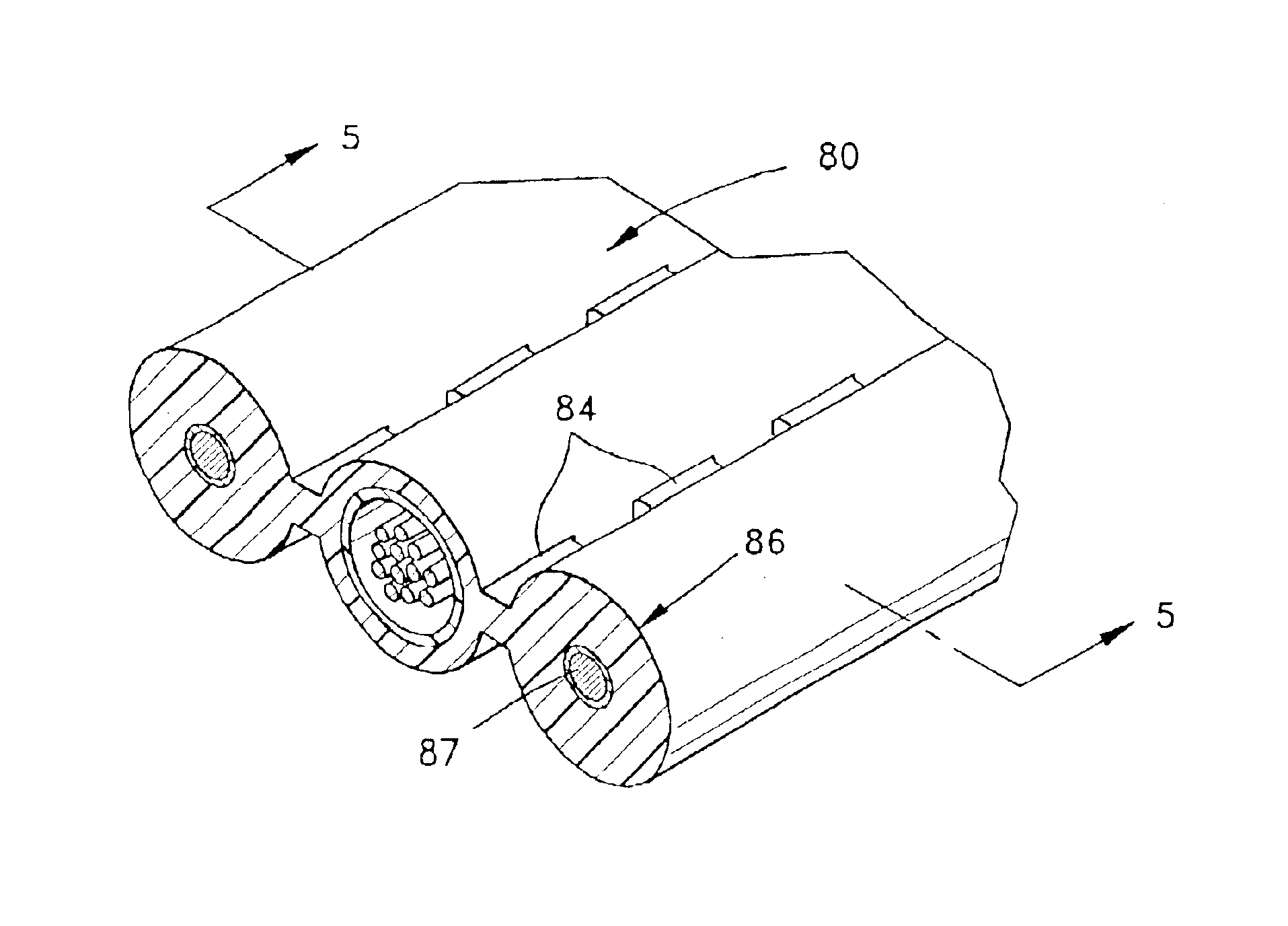
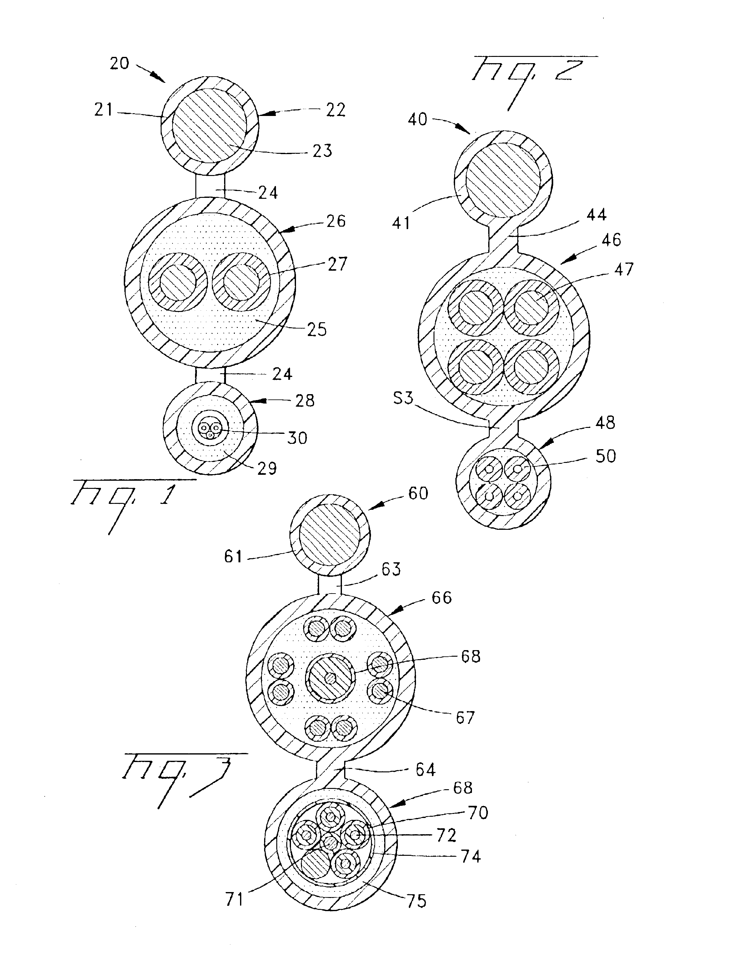
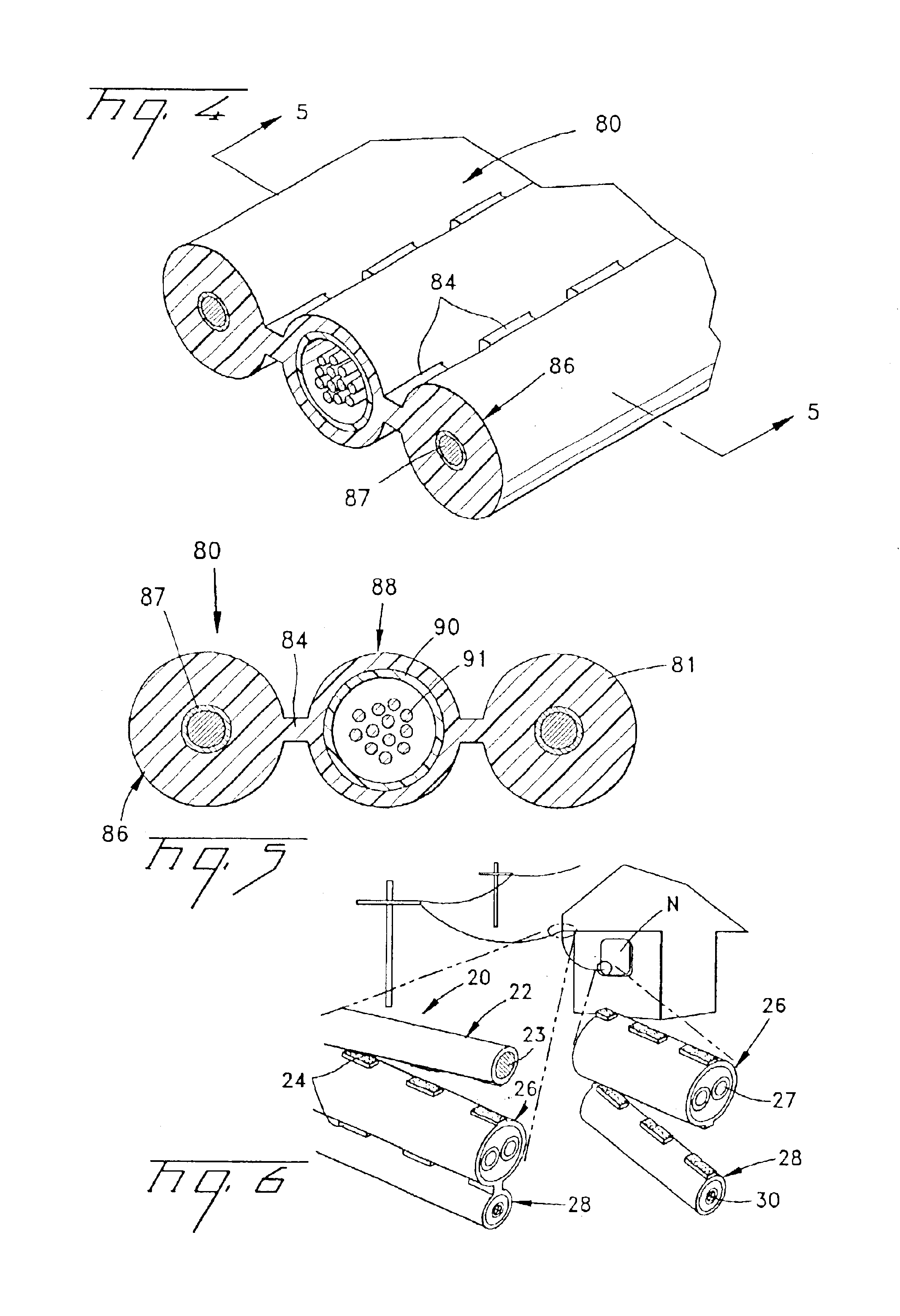
Referring to FIGS. 1-5, exemplary embodiments of fiber optic cables 20,40,60,80 according to the present invention will be described. Fiber optic cable 20 (FIGS. 1 and 7) can be a self-supporting cable that is composed of cable sections, for example, a messenger section 22 and transmission sections 26 and 28. Each cable section preferably comprises a portion of a cable jacket 21 having webs 24 that connect cable sections 22,26,28 together. Messenger section 22 preferably comprises non-metallic and / or metallic strength members, for example, aramid or fiberglass yarns, glass reinforced plastic rods, and / or a steel messenger wire 23. Transmission section 26 preferably comprises at least one transmission component, for example, an electrical / electronic component 27. Transmission component 27 can be, for example, a twisted pair of electrical wires that are preferably surrounded by a layer of strength members 25. Transmission component 27 preferably performs, for example, a data or power ...


PUM

PropertyMeasurementUnit
pressureaaaaaaaaaa
strengthaaaaaaaaaa
opticalaaaaaaaaaa

Abstract

Cables and an apparatus and methods for making cables having at least one messenger section, transmission sections, and at least two series of connecting webs. At least one series of webs can be intermittently formed. The messenger section can include a messenger wire for supporting the cable, and the transmission sections can include electrical / electronic and / or optical transmission components. A method of making cables may include the steps of pulling cable components through a melt cavity having a molten jacketing material therein; defining at least three cable sections by coating the cable components with the molten jacketing material; monolithically forming at least two series of connecting webs made of the molten jacketing material between each cable section during a web-forming mode; and defining intermittent webs by forming longitudinal gaps between the webs of at least one of the series of webs during a gap-forming mode by switching between the web-forming and gap-forming modes with respect to the at least one series of webs. The apparatus includes a melt cavity associated with a die orifice having web-forming sections, and gap forming parts associated with the web-forming sections, the gap forming parts being operative to block the flow of the cable jacketing material for forming gaps defining the webs.

Description

FIELD OF INVENTIONThe present invention relates to cables, and an apparatus and methods for making cables, that can include at least one optical fiber.BACKGROUND OF THE INVENTIONFiber optic cables include at least one optical fiber that can transmit telecommunication information, for example, voice, data, and video information. Self-supporting fiber optic cables are designed for aerial applications and typically include a messenger wire and a core section having conductors therein that may be solely optical or a combination of optical and electrical conductors. Self-supporting fiber optic cables of the FIG. 8 type may be characterized into two general categories, namely, self-supporting cables with a core section having no excess length relative to the messenger wire, and self-supporting cables having a core section having an over-length, typically about 0.2%, relative to the messenger wire. Examples of self-supporting cables having no core section over-length are disclosed in U.S. ...

Claims


Application Information

Patent Timeline
Patent Type & Authority Patents(United States)
IPC IPC(8): G02B6/44H01B11/00H01B11/22H01B7/18H01B13/00H01B13/24
CPCH01B11/22G02B6/4479G02B6/4484G02B6/4422G02B6/4405G02B6/4411G02B6/4416G02B6/4473
Inventor HURLEY, WILLIAM C.COLEMAN, JOHN D.MCALPINE, WARREN W.
Owner CORNING OPTICAL COMM LLC
Learn More