Base station apparatus and radio communication method

a technology of radio communication and base station, which is applied in the direction of power management, transmission monitoring, amplitude demodulation, etc., can solve the problems of deteriorating dsch data quality, affecting the quality of dsch data, and the transmission system of dsch data is not always optimal, so as to prevent the deterioration of dsch data quality

Inactive Publication Date: 2005-01-25
INVT SPE LLC
View PDF14 Cites 87 Cited by
  • Summary
  • Abstract
  • Description
  • Claims
  • Application Information

AI Technical Summary

Benefits of technology

Next, since the TPC commands for 2 frames are transmitted to the base station, the base station calculates an SIR fluctuation amount for 2 frames using the TPC commands, and adds the SIR fluctuation amount to the SIR notified from the communication terminal so as to estimate the SIR at the time at which the DSCH data are received by the communication terminal. Finally, The base station determines the transmission system of the DSCH data based on the estimated SIR. Accordingly, the DSCH data are transmitted to the transmission terminal using the modulating and coding schemes and transmitting power which are optimal for the channel condition at the DSCH data transmitting time so that the quality of the DSCH data can be prevented from being deteriorated.

Problems solved by technology

Therefore, within this two frames period (from t1 to t3), the propagation environment mostly will be changed, and hence, it is possible that the SIR of DSCH data received by a communication terminal is greatly deteriorated.
Since the base station BS has determined the modulating, and coding schemes as well as the transmitting power as the transmission system of DSCH data which are optimal for SIR measured from t1 to t2 and if SIR notified from a communication terminal is different from the SIR of DSCH data, then, the transmission system of DSCH data is not always optimal.
Therefore, there is a possibility that the quality of DSCH data is deteriorated.

Method used


Image

  • Base station apparatus and radio communication method
  • Base station apparatus and radio communication method
  • Base station apparatus and radio communication method

Examples


Embodiment Construction

Referring to the attached drawings, a detailed description of one embodiment of the present invention is given below. However, the following explanation is restricted to the case where DSCH is used as a common channel shared by a plurality of communication terminals, but the present invention is not limited to this restriction and this embodiment is applicable to the case where any channel excluding DSCH can be used as a common channel.

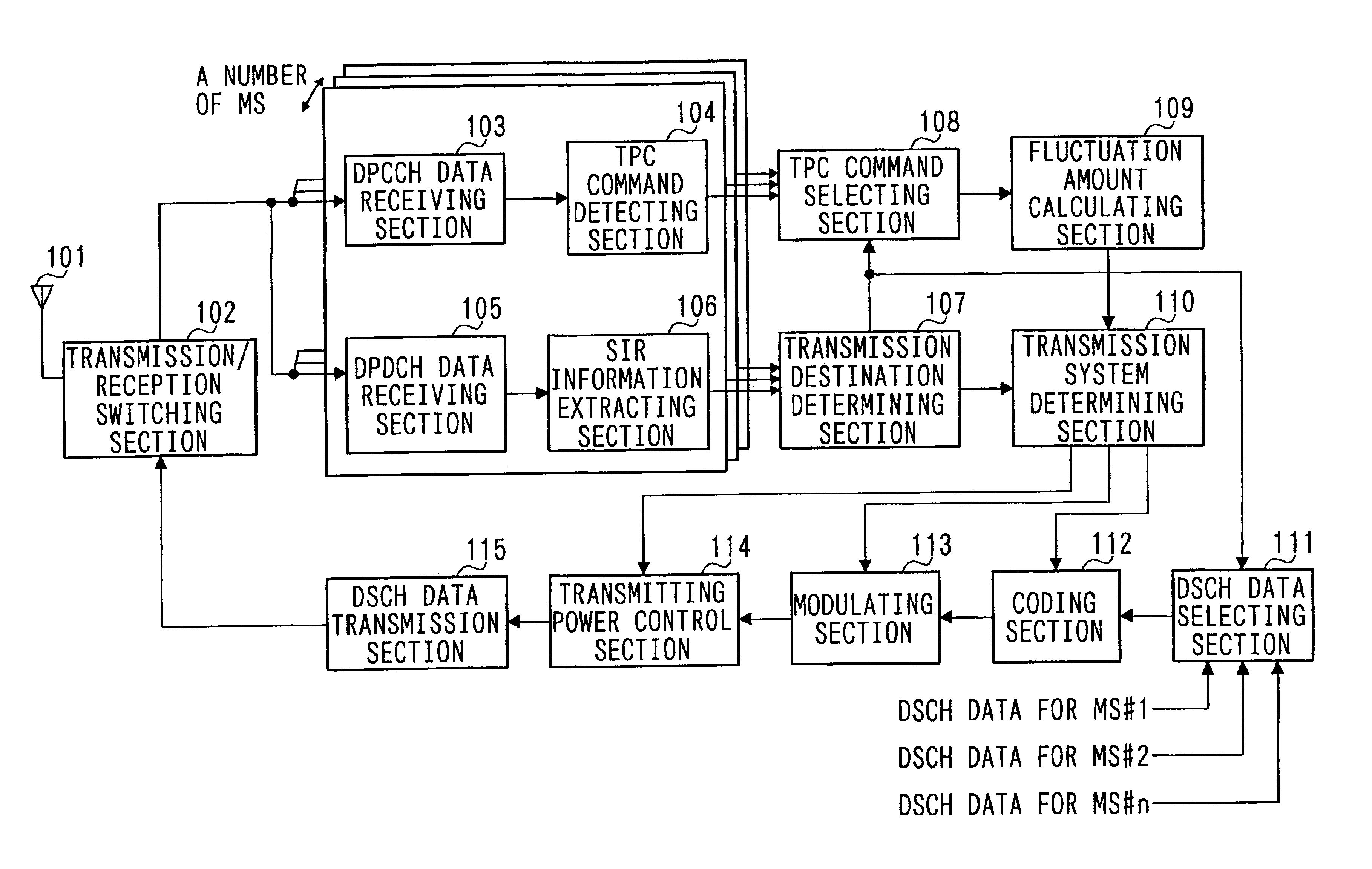
FIG. 3 is a block diagram of a main section illustrating a schematic structure of a base station apparatus according to one embodiment of the present invention. In the base station apparatus shown in FIG. 3, a transmission / reception switching section 102 outputs data received via an antenna 101 to each DPCCH data receiving section 103 and to each DPDCH data receiving section 105, and outputs DSCH data received from a DSCH data transmission section 115 to the antenna 101.

Each DPCCH data receiving section 103 executes a predetermined radio process for t...


PUM


Abstract

An SIR information extracting section 106 extracts SIR measured at a communication terminal from the received data, and a fluctuation amount calculating section 109 calculates a fluctuation amount of SIR between time at which the communication terminal has measured SIR and transmission starting time of DSCH data using a TPC command, and a. transmission system determining section 110 adds the SIR fluctuation amount calculated in the fluctuation amount calculating section 109 to the SIR measured at the communication terminal and estimates SIR of DSCH data so as to determine an optimal transmission system of DSCH data according to the estimated SIR.

Description

TECHNICAL FIELDThe present invention relates to a base station apparatus and a radio communication method used for high-speed data communication.BACKGROUND ARTOne example of a multiple access method of a digital radio communication system is CDMA (Code Division Multiple Access) system. 3GPP (3rd Generation Partnership Project) which is a standard association of the mobile radio communication system adopts, in its standardization, the CDMA system wherein a DSCH (Downlink Shared CHannel) used for high-speed data communication in a downlink (link from a base station to a communication terminal) is defined as one of the common channels shared by a plurality of communication terminals.Since in each communication terminal, the DSCH is allocated to be used in a predetermined transmission unit (for example, each one frame), then it is expected to be utilized for high-speed packet communication, etc., on a downlink.An explanation for a communication procedure of high-speed packet communicati...

Claims


Application Information

Patent Timeline
Patent Type & Authority Patents(United States)
IPC IPC(8): H04L1/00H04B7/005H04B17/00H04W52/08H04W52/14H04W52/22H04W52/24H04W52/26H04W52/32
CPCH04L1/0003H04B17/373H04L1/002H04L1/0026H04L1/0033H04W52/143H04W52/221H04W52/24H04W52/241H04W52/262H04B17/336H04L1/0009H04W52/08H04W52/247H04W52/32
Inventor MIYOSHI, KENICHIAOYAMA, TAKAHISA
Owner INVT SPE LLC
Why Eureka
Try Eureka