
Backboard with removable pad

a backboard and removable technology, applied in the field of removable backboard pads, can solve the problems of soft tissue injury, patient's body may become sore and irritated, and patients must often remain substantially immobilized, and achieve the effect of reasonable comfort and extended heat relief for patients

Inactive Publication Date: 2005-02-01
SCHENCK DAVID
View PDF12 Cites 34 Cited by
  • Summary
  • Abstract
  • Description
  • Claims
  • Application Information

AI Technical Summary

Benefits of technology

The backboard pad of the present invention is comprised of a combination of gel-filled sections and inflatable sections carried on a base pad. It has been found that the combination of gel-filled sections and inflatable sections provide a significant reduction in patient discomfort, while still providing the necessary immobilization.
When used, the backboard pad, which may be rolled or folded for storage, is placed on top of a backboard, with the slip-resistant lower surface of the backboard pad preventing the backboard pad from sliding on the upper surface of the backboard. If desired, the gel-filled pad may be heated prior to use, with the heat retentive properties of the gel being used to provide extended heat relief to the patient. The patient is then placed on the upper surface of the backboard pad, with the patient's head being centered on the head pad, the scapula on the scapula pads, the buttocks on the buttocks pad, and the heels on the heel pad. The restraint straps are then tightened around the patient. The lumbar and knee pads are then inflated until pressure is exerted against the lumbar region and the underside of the knees, respectively. The patient may then be safely moved without danger of significant movement on the backboard, and with reasonable comfort, even for extended periods.

Problems solved by technology

Patients must often remain in a substantially immobilized, uncomfortable position on a backboard for hours until diagnosis and treatment is possible.
During this time, areas of the patient's body may become sore and irritated, and soft tissue injury may result.
Further, the “one size fits all” construction of prior art pads can actually increase patient discomfort.

Method used


Image

  • Backboard with removable pad
  • Backboard with removable pad
  • Backboard with removable pad

Examples


Embodiment Construction

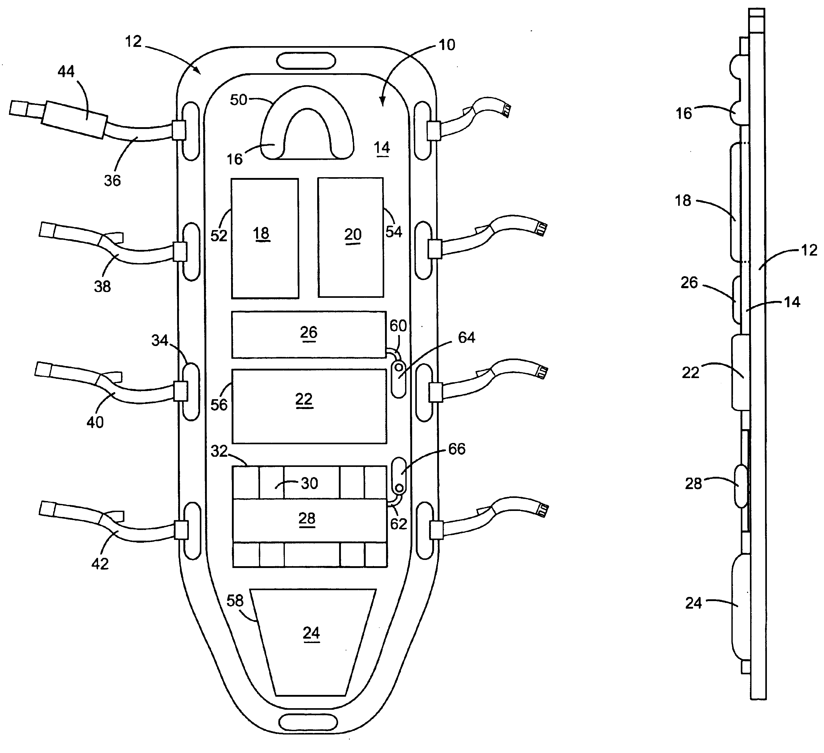
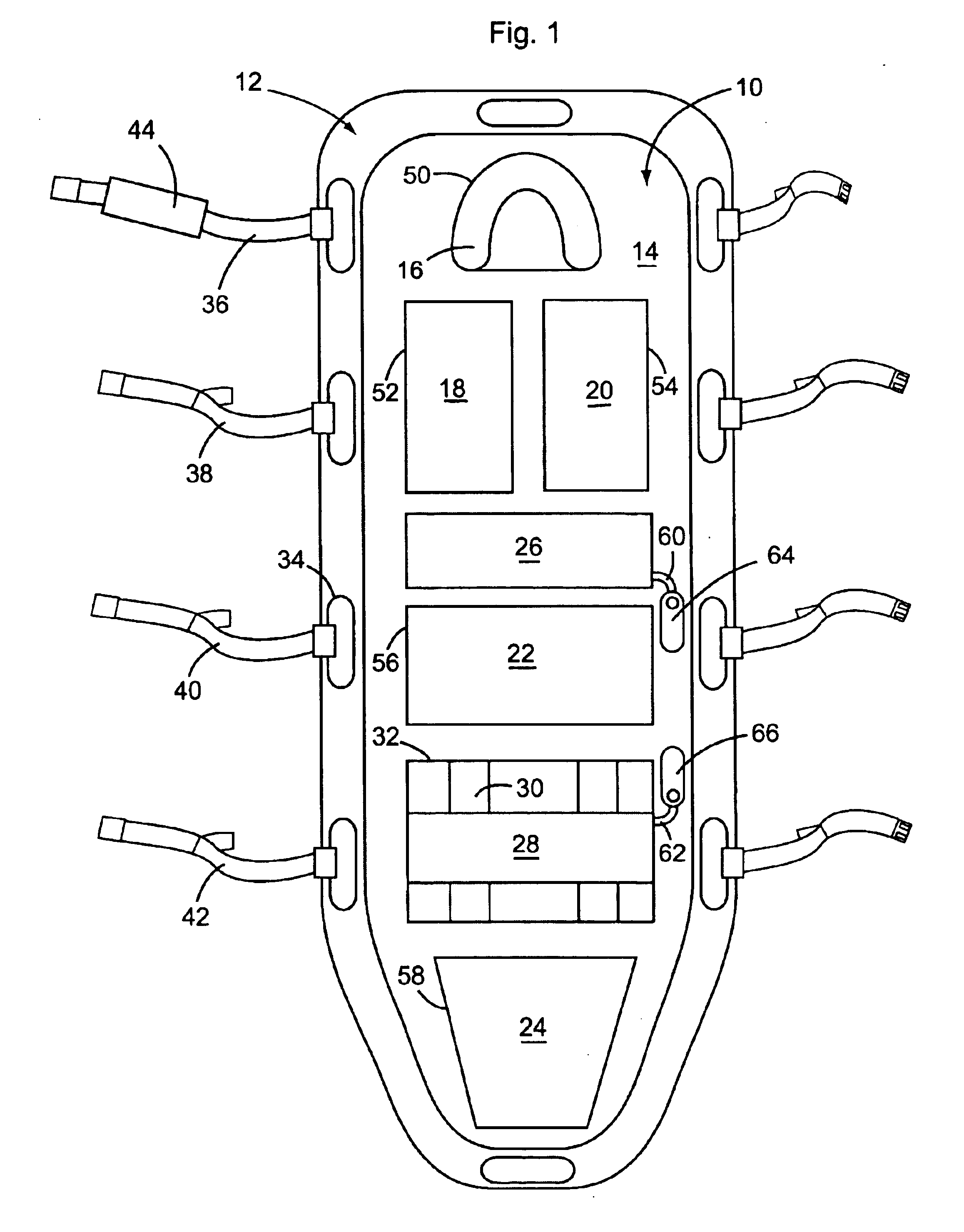
As illustrated, backboard pad, generally 10, adapted to be positioned on a backboard, generally 12, is comprised of a base pad 14 having upper and lower ends, opposed sides, a top surface and a bottom surface, pad 14 carrying a plurality of gel-filled sections and inflatable sections. As identified in the drawings, the gel-filled sections include headrest pad 16, scapula pads 18 and 20, buttocks pad 22, and heel pad 24. The inflatable sections are lumbar pad 26 and knee pad 28, the latter pad being slidably mounted on guide belts 30 within base pad opening 32.

Backboard 12 includes opposed sides spaced outwardly from the top, bottom and sides of pad 10, a top surface and a bottom surface, and spaced handholds 34 extending through backboard 12 between its top and bottom surfaces. A plurality of restraint belts 36, 38, 40 and 42 are attachable over pad 10 to secure a patient onto pad 10. Belt 36, used to secure a patient's head in an immobilized position on head pad 16, includes a gel-...


PUM


Abstract

Improved backboard pads for use in transporting immobilized patients on a backboard while still providing reasonable comfort to the patient include a base pad having with a plurality of gel-filled pads secured to the base pad, the gel-filled pads including first and second scapula pads positioned on either side of the longitudinal axis of the base pad, a buttocks pad between the scapula pads and the lower end of the base pad, a heel pad between the buttocks pad and the lower end of the base pad, and a headrest pad between the scapula pads and the upper end of the base pad. An inflatable lumbar pad is secured to the base pad between the scapula pads and the buttocks pad; and an inflatable knee pad is slidably positioned between the buttocks pad and the heel pad. The gel-filled pads are preferable secured in openings through the base pad.

Description

BACKGROUND OF THE INVENTION(1) Field of the InventionThe present invention relates generally to a removable pad for placement on a backboard, and in particular to a removable backboard pad that provides comfortable support to patients of different physical dimensions while holding the patient in an immobilized position.(2) Description of the Prior ArtBackboards, also known as spine boards, are used to transport injured patients, especially patients who may have suffered a spinal injury. To be effective, the backboard must hold the patient in an immobilized position to prevent further injury. A backboard is comprised of a rigid board having a generally planar upper surface dimensioned to extend beyond an average adult's height and width, with handholds spaced along each side, and optionally the top and bottom, of the board. The backboard may be constructed of metal, wood or a rigid plastic. Restraining straps across are used to secure the patient to the board in a face-up position.Pa...

Claims


Application Information

Patent Timeline
IPC IPC(8): A61G1/00A61G1/04
CPCA61G1/04A61G1/00
Inventor SCHENCK, DAVID
Owner SCHENCK DAVID
Learn More